Rendering or image synthesis is the automatic process of generating a photorealistic or non-photorealistic image from a 2D or 3D model by means of computer programs. Also, the results of displaying such a model can be called a render. A scene file contains objects in a strictly defined language or data structure; it would contain geometry, viewpoint, texture, lighting, and shading information as a description of the virtual scene. The data contained in the scene file is then passed to a rendering program to be processed and output to a digital image or raster graphics image file. The term "rendering" may be by analogy with an "artist's rendering" of a scene.

Global illumination, or indirect illumination is a group of algorithms used in 3D computer graphics that are meant to add more realistic lighting to 3D scenes. Such algorithms take into account not only the light that comes directly from a light source, but also subsequent cases in which light rays from the same source are reflected by other surfaces in the scene, whether reflective or not.

In 3D computer graphics, radiosity is an application of the finite element method to solving the rendering equation for scenes with surfaces that reflect light diffusely. Unlike rendering methods that use Monte Carlo algorithms, which handle all types of light paths, typical radiosity only account for paths which leave a light source and are reflected diffusely some number of times before hitting the eye. Radiosity is a global illumination algorithm in the sense that the illumination arriving on a surface comes not just directly from the light sources, but also from other surfaces reflecting light. Radiosity is viewpoint independent, which increases the calculations involved, but makes them useful for all viewpoints.

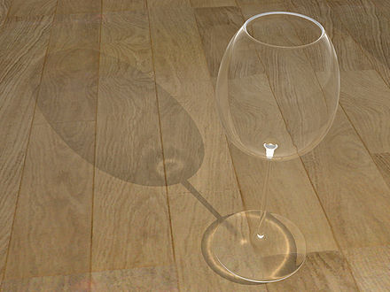
In computer graphics, ray tracing is a rendering technique for generating an image by tracing the path of light as pixels in an image plane and simulating the effects of its encounters with virtual objects. The technique is capable of producing a high degree of visual realism, more so than typical scanline rendering methods, but at a greater computational cost. This makes ray tracing best suited for applications where taking a relatively long time to render can be tolerated, such as in still computer-generated images, and film and television visual effects (VFX), but more poorly suited to real-time applications such as video games, where speed is critical in rendering each frame.

Ray casting is the use of ray–surface intersection tests to solve a variety of problems in 3D computer graphics and computational geometry. The term was first used in computer graphics in a 1982 paper by Scott Roth to describe a method for rendering constructive solid geometry models.
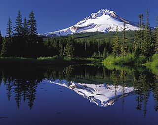
Reflection is the change in direction of a wavefront at an interface between two different media so that the wavefront returns into the medium from which it originated. Common examples include the reflection of light, sound and water waves. The law of reflection says that for specular reflection the angle at which the wave is incident on the surface equals the angle at which it is reflected. Mirrors exhibit specular reflection.
Diffuse reflection is the reflection of light or other waves or particles from a surface such that a ray incident on the surface is scattered at many angles rather than at just one angle as in the case of specular reflection. An ideal diffuse reflecting surface is said to exhibit Lambertian reflection, meaning that there is equal luminance when viewed from all directions lying in the half-space adjacent to the surface.

YafaRay is a free and open-source ray tracing program that uses an XML scene description language. There is a YafaRay addon for the 3D modelling and animation software known as Blender 2.78. The ray tracer is licensed under the GNU Lesser General Public License (LGPL).
In computer graphics, the rendering equation is an integral equation in which the equilibrium radiance leaving a point is given as the sum of emitted plus reflected radiance under a geometric optics approximation. It was simultaneously introduced into computer graphics by David Immel et al. and James Kajiya in 1986. The various realistic rendering techniques in computer graphics attempt to solve this equation.

In computer graphics, ambient occlusion is a shading and rendering technique used to calculate how exposed each point in a scene is to ambient lighting. For example, the interior of a tube is typically more occluded than the exposed outer surfaces, and the deeper you go inside the tube, the more occluded the lighting becomes. Ambient occlusion can be seen as an accessibility value that is calculated for each surface point. In scenes with open sky this is done by estimating the amount of visible sky for each point, while in indoor environments only objects within a certain radius are taken into account and the walls are assumed to be the origin of the ambient light. The result is a diffuse, non-directional shading effect that casts no clear shadows but that darkens enclosed and sheltered areas and can affect the rendered image's overall tone. It is often used as a post-processing effect.
Beam tracing is an algorithm to simulate wave propagation. It was developed in the context of computer graphics to render 3D scenes, but it has been also used in other similar areas such as acoustics and electromagnetism simulations.

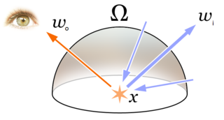
The bidirectional reflectance distribution function is a function of four real variables that defines how light is reflected at an opaque surface. It is employed in the optics of real-world light, in computer graphics algorithms, and in computer vision algorithms. The function takes an incoming light direction, , and outgoing direction, , and returns the ratio of reflected radiance exiting along to the irradiance incident on the surface from direction . Each direction is itself parameterized by azimuth angle and zenith angle , therefore the BRDF as a whole is a function of 4 variables. The BRDF has units sr−1, with steradians (sr) being a unit of solid angle.
In computer graphics, environment mapping, or reflection mapping, is an efficient image-based lighting technique for approximating the appearance of a reflective surface by means of a precomputed texture image. The texture is used to store the image of the distant environment surrounding the rendered object.

Path tracing is a computer graphics Monte Carlo method of rendering images of three-dimensional scenes such that the global illumination is faithful to reality. Fundamentally, the algorithm is integrating over all the illuminance arriving to a single point on the surface of an object. This illuminance is then reduced by a surface reflectance function (BRDF) to determine how much of it will go towards the viewpoint camera. This integration procedure is repeated for every pixel in the output image. When combined with physically accurate models of surfaces, accurate models of real light sources, and optically correct cameras, path tracing can produce still images that are indistinguishable from photographs.
3D rendering is the 3D computer graphics process of converting 3D models into 2D images on a computer. 3D renders may include photorealistic effects or non-photorealistic styles.
Computer graphics lighting is the collection of techniques used to simulate light in computer graphics scenes. While lighting techniques offer flexibility in the level of detail and functionality available, they also operate at different levels of computational demand and complexity. Graphics artists can choose from a variety of light sources, models, shading techniques, and effects to suit the needs of each application.

Kerkythea is a standalone rendering system that supports raytracing and Metropolis light transport, uses physically accurate materials and lighting, and is distributed as freeware. Currently, the program can be integrated with any software that can export files in obj and 3ds formats, including 3ds Max, Blender, LightWave 3D, SketchUp, Silo and Wings3D.

Within the field of computer graphics, unbiased rendering refers to any rendering technique that does not introduce systematic error, or bias, into the radiance approximation. The term refers to statistical bias, not the broader meaning of subjective bias. Because of this, an unbiased rendering technique can produce a reference image to compare against renders that use other techniques. Path tracing and its derivatives can be unbiased, whereas ray tracing was originally biased.
Volumetric path tracing is a method for rendering images in computer graphics which was first introduced by Lafortune and Willems. This method enhances the rendering of the lighting in a scene by extending the path tracing method with the effect of light scattering. It is used for photorealistic effects of participating media like fire, explosions, smoke, clouds, fog or soft shadows.