
A jet engine is a type of reaction engine, discharging a fast-moving jet of heated gas that generates thrust by jet propulsion. While this broad definition may include rocket, water jet, and hybrid propulsion, the term jet engine typically refers to an internal combustion air-breathing jet engine such as a turbojet, turbofan, ramjet, pulse jet, or scramjet. In general, jet engines are internal combustion engines.

A rocket is a vehicle that uses jet propulsion to accelerate without using any surrounding air. A rocket engine produces thrust by reaction to exhaust expelled at high speed. Rocket engines work entirely from propellant carried within the vehicle; therefore a rocket can fly in the vacuum of space. Rockets work more efficiently in a vacuum and incur a loss of thrust due to the opposing pressure of the atmosphere.

A heat exchanger is a system used to transfer heat between a source and a working fluid. Heat exchangers are used in both cooling and heating processes. The fluids may be separated by a solid wall to prevent mixing or they may be in direct contact. They are widely used in space heating, refrigeration, air conditioning, power stations, chemical plants, petrochemical plants, petroleum refineries, natural-gas processing, and sewage treatment. The classic example of a heat exchanger is found in an internal combustion engine in which a circulating fluid known as engine coolant flows through radiator coils and air flows past the coils, which cools the coolant and heats the incoming air. Another example is the heat sink, which is a passive heat exchanger that transfers the heat generated by an electronic or a mechanical device to a fluid medium, often air or a liquid coolant.

A scramjet is a variant of a ramjet airbreathing jet engine in which combustion takes place in supersonic airflow. As in ramjets, a scramjet relies on high vehicle speed to compress the incoming air forcefully before combustion, but whereas a ramjet decelerates the air to subsonic velocities before combustion using shock cones, a scramjet has no shock cone and slows the airflow using shockwaves produced by its ignition source in place of a shock cone. This allows the scramjet to operate efficiently at extremely high speeds.
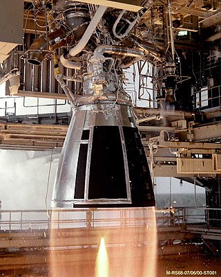
A rocket engine uses stored rocket propellants as the reaction mass for forming a high-speed propulsive jet of fluid, usually high-temperature gas. Rocket engines are reaction engines, producing thrust by ejecting mass rearward, in accordance with Newton's third law. Most rocket engines use the combustion of reactive chemicals to supply the necessary energy, but non-combusting forms such as cold gas thrusters and nuclear thermal rockets also exist. Vehicles propelled by rocket engines are commonly used by ballistic missiles and rockets. Rocket vehicles carry their own oxidiser, unlike most combustion engines, so rocket engines can be used in a vacuum to propel spacecraft and ballistic missiles.
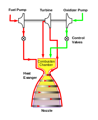
The expander cycle is a power cycle of a bipropellant rocket engine. In this cycle, the fuel is used to cool the engine's combustion chamber, picking up heat and changing phase. The now heated and gaseous fuel then powers the turbine that drives the engine's fuel and oxidizer pumps before being injected into the combustion chamber and burned.
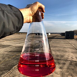
RP-1 (alternatively, Rocket Propellant-1 or Refined Petroleum-1) is a highly refined form of kerosene outwardly similar to jet fuel, used as rocket fuel. RP-1 provides a lower specific impulse than liquid hydrogen (H2), but is cheaper, is stable at room temperature, and presents a lower explosion hazard. RP-1 is far denser than H2, giving it a higher energy density (though its specific energy is lower). RP-1 also has a fraction of the toxicity and carcinogenic hazards of hydrazine, another room-temperature liquid fuel.

A liquid-propellant rocket or liquid rocket uses a rocket engine burning liquid propellants. (Alternate approaches use gaseous or solid propellants.) Liquids are desirable propellants because they have reasonably high density and their combustion products have high specific impulse (Isp). This allows the volume of the propellant tanks to be relatively low.

The RS-25, also known as the Space Shuttle Main Engine (SSME), is a liquid-fuel cryogenic rocket engine that was used on NASA's Space Shuttle and is used on the Space Launch System (SLS).

The J-2, commonly known as Rocketdyne J-2, was a liquid-fuel cryogenic rocket engine used on NASA's Saturn IB and Saturn V launch vehicles. Built in the United States by Rocketdyne, the J-2 burned cryogenic liquid hydrogen (LH2) and liquid oxygen (LOX) propellants, with each engine producing 1,033.1 kN (232,250 lbf) of thrust in vacuum. The engine's preliminary design dates back to recommendations of the 1959 Silverstein Committee. Rocketdyne won approval to develop the J-2 in June 1960 and the first flight, AS-201, occurred on 26 February 1966. The J-2 underwent several minor upgrades over its operational history to improve the engine's performance, with two major upgrade programs, the de Laval nozzle-type J-2S and aerospike-type J-2T, which were cancelled after the conclusion of the Apollo program.
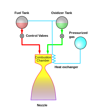
The pressure-fed engine is a class of rocket engine designs. A separate gas supply, usually helium, pressurizes the propellant tanks to force fuel and oxidizer to the combustion chamber. To maintain adequate flow, the tank pressures must exceed the combustion chamber pressure.
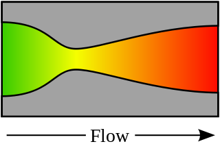
A rocket engine nozzle is a propelling nozzle used in a rocket engine to expand and accelerate combustion products to high supersonic velocities.
RD-270 (Russian: Раке́тный дви́гатель 270, Rocket Engine 270, 8D420) was a single-chamber liquid-bipropellant rocket engine designed by Energomash (USSR) in 1960–1970. It was to be used on the first stages of proposed heavy-lift UR-700 and UR-900 rocket families, as well as on the N1. It has the highest thrust among single-chamber engines of the USSR, 640 metric tons at the surface of Earth. The propellants used are unsymmetrical dimethylhydrazine (UDMH) and nitrogen tetroxide (N2O4). The chamber pressure was among the highest considered, being about 26 MPa. This was achieved by applying full-flow staged combustion cycle for all the incoming mass of fuel, which is turned into a gas and passes through multiple turbines before being burned in the combustion chamber. This allowed the engine to achieve a specific impulse of 301 s (2.95 km/s) at the Earth's surface.
The YF-75 is a liquid cryogenic rocket engine burning liquid hydrogen and liquid oxygen in a gas generator cycle. It is China's second generation of cryogenic propellant engine, after the YF-73, which it replaced. It is used in a dual engine mount in the H-18 third stage of the Long March 3A, Long March 3B and Long March 3C launch vehicles. Within the mount, each engine can gimbal individually to enable thrust vectoring control. The engine also heats hydrogen and helium to pressurize the stage tanks and can control the mixture ratio to optimize propellant consumption.
A cold gas thruster is a type of rocket engine which uses the expansion of a pressurized gas to generate thrust. As opposed to traditional rocket engines, a cold gas thruster does not house any combustion and therefore has lower thrust and efficiency compared to conventional monopropellant and bipropellant rocket engines. Cold gas thrusters have been referred to as the "simplest manifestation of a rocket engine" because their design consists only of a fuel tank, a regulating valve, a propelling nozzle, and the little required plumbing. They are the cheapest, simplest, and most reliable propulsion systems available for orbital maintenance, maneuvering and attitude control.
Characteristic velocity or , or C-star is a measure of the combustion performance of a rocket engine independent of nozzle performance, and is used to compare different propellants and propulsion systems. c* should not be confused with c, which is the effective exhaust velocity related to the specific impulse by: . Specific impulse and effective exhaust velocity are dependent on the nozzle design unlike the characteristic velocity, explaining why C-star is an important value when comparing different propulsion system efficiencies. c* can be useful when comparing actual combustion performance to theoretical performance in order to determine how completely chemical energy release occurred. This is known as c*-efficiency.

A cryogenic rocket engine is a rocket engine that uses a cryogenic fuel and oxidizer; that is, both its fuel and oxidizer are gases which have been liquefied and are stored at very low temperatures. These highly efficient engines were first flown on the US Atlas-Centaur and were one of the main factors of NASA's success in reaching the Moon by the Saturn V rocket.

Rocket propellant is used as reaction mass ejected from a rocket engine to produce thrust. The energy required can either come from the propellants themselves, as with a chemical rocket, or from an external source, as with ion engines.

TM65 is a rocket engine developed by Copenhagen Suborbitals. TM65 uses Ethanol and liquid oxygen as propellants in a pressure-fed power cycle.

The RD-0110 is a rocket engine burning liquid oxygen and kerosene in a gas generator combustion cycle. It has four fixed nozzles and the output of the gas generator is directed to four secondary vernier nozzles to provide attitude control for the stage. It has an extensive flight history with its initial versions having flown more than 64 years ago.


