Two-tone testing

Last updated
A spectrum analyser - typically used as the measuring instrument in two-tone testing HP-8560E-Spectrum-Analyzer 22.jpg
A spectrum analyser – typically used as the measuring instrument in two-tone testing

Two-tone testing is a means of testing electronic components and systems, particularly radio systems, for intermodulation distortion. It consists of simultaneously injecting two sinusoidal signals of different frequencies (tones) into the component or system. Intermodulation distortion usually occurs in active components like amplifiers, but can also occur in some circumstances in passive items such as cable connectors, especially at high power.

Contents

Measurement in two-tone testing is most commonly done by examining the output of the device under test (DUT) with a spectrum analyser with which intermodulation products can be directly observed. Sometimes this is not possible with complete systems and instead the consequences of intermodulation are observed. For instance, in a radar system the result of intermodulation might be the generation of false targets.

Rationale

An electronic device can be tested by applying a single frequency to its input and measuring the response at its output. If there is any non-linearity in the device, this will cause harmonic distortion at the output. This kind of distortion consists of whole-number multiples of the applied signal frequency, as well as the original frequency being present at the device output. Intermodulation distortion can produce outputs at other frequencies. The new frequencies created by intermodulation are the sum and difference of the injected frequencies and the harmonics of these. Intermodulation effects cannot be detected with single-tone testing, but they may be just as, or more undesirable than harmonic distortion depending on their frequency and level. [1]

Two-tone testing can also be used to determine the discrimination of a radio receiver. That is, the ability of the receiver to distinguish between transmissions close in frequency. [2]

Testing

General test setup for two-tone testing Two tone general test.svg
General test setup for two-tone testing

Component testing

Circuit components such as amplifiers can be tested using the two-tone method with a test setup like that shown in the figure. Two signal generators, set to two different frequencies F1 and F2, are fed into a power combiner through circulators. The combiner needs to have good isolation to prevent the signal from one generator being sent to the output of the other. If this happens, intermodulation can occur in the non-linear parts of the generator internal circuit. The resulting intermodulation products will give a false result to the test. The circulators are there to provide even more isolation between the generators and isolation between any signal that might get reflected back from the device under test (DUT) and the generator. The circulators have one port connected to a resistive load so that they act as isolators. Low-pass filters may also be provided at the generator outputs to remove any harmonic distortion. These harmonics could cause unexpected intermodulation products in the DUT, again giving misleading results. The output of the DUT is fed to a spectrum analyser where the results are observed, possibly via an attenuator to reduce the signal to a level the instrument can cope with. [3]

Passive components

Passive components such as cables, connectors and antennas, are generally expected to be linear and therefore not liable to generate any intermodulation. However, especially at high power, a number of effects can lead to non-linearity through formation of a metal–semiconductor junction at what is supposed to be a metal-metal junction. These effects include corrosion, surface oxidisation, dirtiness, and simple failure to fully make mechanical contact. Some passive materials are intrinsically non-linear. These include ferrites, ferrous metals, and carbon-fibre composites. [4]

Intermodulation distortion is a particularly difficult problem at the cellular base stations of mobile phone cellular networks. These have to deal with multiple transmissions at closely spaced frequencies and it is necessary to ensure that these do not interact with each other. A typical specification is that intermodulation products should not exceed −125 dBm in the presence of 40 dbm transmissions. This equates to a requirement for a signal to intermodulation ratio of 165 dB, an exceedingly stringent specification. To achieve this, materials and components must be chosen with great care and installation and maintenance done to a high standard. Likewise, two-tone testing of these components needs to be done with great care and precision since intermodulation products at these low levels can easily be generated within the test setup accidentally. [5]

There is an international standard, IEC 62037 "Passive RF and microwave devices, intermodulation level measurement", for measuring intermodualtion distortion of passive components. Testing to the standard ensures that specifications from different manufacturers are done under the same conditions and can be compared with each other. [6] Militaries will typically use their own standards for testing. For instance US procurement contracts may specify MIL-STD-461. [7]

Receiver testing

Two-tone receiver testing using direct injection Two tone Rx test (direct).svg
Two-tone receiver testing using direct injection
Two-tone receiver testing using off-air method Two tone Rx test (off air).svg
Two-tone receiver testing using off-air method

A test setup suitable for testing receivers at microwave frequencies is shown in the figure. The two signal generators, F1 and F2, are combined using a directional coupler in reverse. That is, the two generators are connected to what would normally be the coupled and transmitted output ports respectively. The combined signal appears at what would normally be the input port. The advantage of using a directional coupler rather than a simple summing circuit is that the directional coupler provides isolation between the two generators. As with the component testing, another signal being injected into the output of a signal generator can cause intermodulation distortion within the generator. Isolators are included in the test set up as with the component testing. [10]

The combined test signal can be injected directly in to the receiver if the antenna is removable. A second directional coupler, connected in the conventional configuration, can be used to provide a feed of the input to a spectrum analyser. This allows confirmation that the input signal is free of intermodulation products. If the test signal cannot be directly injected, for instance, because the receiver uses an active antenna, then the test signal is transmitted through its own transmitting antenna. A feed for a spectrum analyser can be provided by connecting a receiving antenna to its input. Tests done by the latter method are normally performed in an anechoic chamber to avoid broadcasting the test signal to the world at large. [11]

The consequences of intermodulation distortion depend on the nature and purpose of the receiver. For a set receiving audio, it can manifest itself as an interfering signal making the wanted station unintelligible. In a radar receiver, it can manifest as a false detection of a target. [12]

Transmitter testing

For transmitters that are designed for the transmission of speech or music, two frequencies within the audio band can be injected into the normal input of the transmitter. The output of the transmitter can be examined with a spectrum analyzer to look for intermodulation products. This kind of end-to-end testing tests all parts of the transmitter for non-linearity: from the audio stage, through the mixing and IF amplifier, to the final RF power amplifier. Likewise, a transmitter used for passing data can be injected with two frequencies within the baseband of the data stream. In some cases, there is no accessible input to a transmitter. Radar transmitters, for instance, do not take an input; the circuitry generating the radar signal is internal to the transmitter. In such cases the tones must be injected at some internal point of the device, or else the amplifiers and other stages must be tested as separate components. [13] A dummy load may be connected to the output of the transmitter to prevent it actually broadcasting, and a directional coupler, possibly together with an attenuator, used to provide a feed to the spectrum analyser. [14]

The spacing in frequency between the two tones is of some significance in transmitter testing. The spacing determines whether intermodulation products are going to be in-band or out-of-band. That is, whether or not they occur within the band that the transmitter is designed to operate. In-band intermodulation is problematic because it interferes with the operation of the transmitter. However, out-of-band intermodulation can be an even greater problem. In most countries the telecommunications authority licenses the operator to use specific frequencies. Out-of-band signals are required to be virtually suppressed altogether. However, the greater frequency difference between the wanted and unwanted signal makes out-of-band intermodulation products relatively easy to remove with filters. [15]

Just as two tones provide a more realistic test than a single tone, multi-tone testing can be used to even better simulate the behaviour of a real signal. The idea is to spread the tones over the bandwidth of the real signal with a similar frequency power density. For accurate results, it is important that the phase of the tones relative to each other is considered. It is usually undesirable that the tones are in a synchronised phase relationship as this can give misleading results. For this reason, it is often endeavoured to generate tones with random phases in multi-tone testing. [16]

Related Research Articles

An electronic oscillator is an electronic circuit that produces a periodic, oscillating or alternating current (AC) signal, usually a sine wave, square wave or a triangle wave, powered by a direct current (DC) source. Oscillators are found in many electronic devices, such as radio receivers, television sets, radio and television broadcast transmitters, computers, computer peripherals, cellphones, radar, and many other devices.

<span class="mw-page-title-main">Amplifier</span> Electronic device/component that increases the strength of a signal

An amplifier, electronic amplifier or (informally) amp is an electronic device that can increase the magnitude of a signal. It is a two-port electronic circuit that uses electric power from a power supply to increase the amplitude of a signal applied to its input terminals, producing a proportionally greater amplitude signal at its output. The amount of amplification provided by an amplifier is measured by its gain: the ratio of output voltage, current, or power to input. An amplifier is defined as a circuit that has a power gain greater than one.

Amplitude distortion is distortion occurring in a system, subsystem, or device when the output amplitude is not a linear function of the input amplitude under specified conditions.

In signal processing, distortion is the alteration of the original shape of a signal. In communications and electronics it means the alteration of the waveform of an information-bearing signal, such as an audio signal representing sound or a video signal representing images, in an electronic device or communication channel.

In telecommunications, a third-order intercept point (IP3 or TOI) is a specific figure of merit associated with the more general third-order intermodulation distortion (IMD3), which is a measure for weakly nonlinear systems and devices, for example receivers, linear amplifiers and mixers. It is based on the idea that the device nonlinearity can be modeled using a low-order polynomial, derived by means of Taylor series expansion. The third-order intercept point relates nonlinear products caused by the third-order nonlinear term to the linearly amplified signal, in contrast to the second-order intercept point that uses second-order terms.

The total harmonic distortion is a measurement of the harmonic distortion present in a signal and is defined as the ratio of the sum of the powers of all harmonic components to the power of the fundamental frequency. Distortion factor, a closely related term, is sometimes used as a synonym.

A signal generator is one of a class of electronic devices that generates electrical signals with set properties of amplitude, frequency, and wave shape. These generated signals are used as a stimulus for electronic measurements, typically used in designing, testing, troubleshooting, and repairing electronic or electroacoustic devices, though it often has artistic uses as well.

<span class="mw-page-title-main">Audio power amplifier</span> Audio amplifier with power output sufficient to drive a loudspeaker

An audio power amplifier amplifies low-power electronic audio signals, such as the signal from a radio receiver or an electric guitar pickup, to a level that is high enough for driving loudspeakers or headphones. Audio power amplifiers are found in all manner of sound systems including sound reinforcement, public address, home audio systems and musical instrument amplifiers like guitar amplifiers. It is the final electronic stage in a typical audio playback chain before the signal is sent to the loudspeakers.

A low-noise amplifier (LNA) is an electronic component that amplifies a very low-power signal without significantly degrading its signal-to-noise ratio (SNR). Any electronic amplifier will increase the power of both the signal and the noise present at its input, but the amplifier will also introduce some additional noise. LNAs are designed to minimize that additional noise, by choosing special components, operating points, and circuit topologies. Minimizing additional noise must balance with other design goals such as power gain and impedance matching.

<span class="mw-page-title-main">Audio system measurements</span> Means of quantifying system performance

Audio system measurements are a means of quantifying system performance. These measurements are made for several purposes. Designers take measurements so that they can specify the performance of a piece of equipment. Maintenance engineers make them to ensure equipment is still working to specification, or to ensure that the cumulative defects of an audio path are within limits considered acceptable. Audio system measurements often accommodate psychoacoustic principles to measure the system in a way that relates to human hearing.

<span class="mw-page-title-main">Spectrum analyzer</span> Electronic testing device

A spectrum analyzer measures the magnitude of an input signal versus frequency within the full frequency range of the instrument. The primary use is to measure the power of the spectrum of known and unknown signals. The input signal that most common spectrum analyzers measure is electrical; however, spectral compositions of other signals, such as acoustic pressure waves and optical light waves, can be considered through the use of an appropriate transducer. Spectrum analyzers for other types of signals also exist, such as optical spectrum analyzers which use direct optical techniques such as a monochromator to make measurements.

<span class="mw-page-title-main">Valve amplifier</span> Type of electronic amplifier

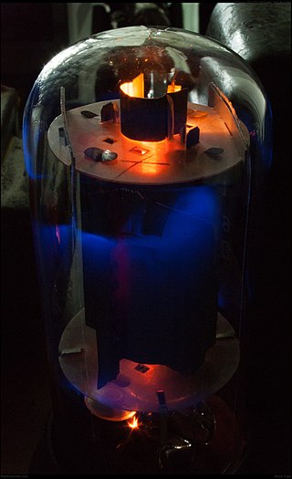
A valve amplifier or tube amplifier is a type of electronic amplifier that uses vacuum tubes to increase the amplitude or power of a signal. Low to medium power valve amplifiers for frequencies below the microwaves were largely replaced by solid state amplifiers in the 1960s and 1970s. Valve amplifiers can be used for applications such as guitar amplifiers, satellite transponders such as DirecTV and GPS, high quality stereo amplifiers, military applications and very high power radio and UHF television transmitters.

<span class="mw-page-title-main">Intermodulation</span> Non-linear effect in amplitude modulation

Intermodulation (IM) or intermodulation distortion (IMD) is the amplitude modulation of signals containing two or more different frequencies, caused by nonlinearities or time variance in a system. The intermodulation between frequency components will form additional components at frequencies that are not just at harmonic frequencies of either, like harmonic distortion, but also at the sum and difference frequencies of the original frequencies and at sums and differences of multiples of those frequencies.

<span class="mw-page-title-main">Voltage-controlled oscillator</span> Oscillator with frequency controlled by a voltage input

A voltage-controlled oscillator (VCO) is an electronic oscillator whose oscillation frequency is controlled by a voltage input. The applied input voltage determines the instantaneous oscillation frequency. Consequently, a VCO can be used for frequency modulation (FM) or phase modulation (PM) by applying a modulating signal to the control input. A VCO is also an integral part of a phase-locked loop. VCOs are used in synthesizers to generate a waveform whose pitch can be adjusted by a voltage determined by a musical keyboard or other input.

In electronics, a frequency multiplier is an electronic circuit that generates an output signal and that output frequency is a harmonic (multiple) of its input frequency. Frequency multipliers consist of a nonlinear circuit that distorts the input signal and consequently generates harmonics of the input signal. A subsequent bandpass filter selects the desired harmonic frequency and removes the unwanted fundamental and other harmonics from the output.

<span class="mw-page-title-main">Network analyzer (electrical)</span> Instrument that measures the network parameters of electrical networks

A network analyzer is an instrument that measures the network parameters of electrical networks. Today, network analyzers commonly measure s–parameters because reflection and transmission of electrical networks are easy to measure at high frequencies, but there are other network parameter sets such as y-parameters, z-parameters, and h-parameters. Network analyzers are often used to characterize two-port networks such as amplifiers and filters, but they can be used on networks with an arbitrary number of ports.

A radio transmitter or just transmitter is an electronic device which produces radio waves with an antenna. Radio waves are electromagnetic waves with frequencies between about 30 Hz and 300 GHz. The transmitter itself generates a radio frequency alternating current, which is applied to the antenna. When excited by this alternating current, the antenna radiates radio waves. Transmitters are necessary parts of all systems that use radio: radio and television broadcasting, cell phones, wireless networks, radar, two way radios like walkie talkies, radio navigation systems like GPS, remote entry systems, among numerous other uses.

Gain compression is a reduction in differential or slope gain caused by nonlinearity of the transfer function of an amplifying device for large-signal inputs.

<span class="mw-page-title-main">Distortion (music)</span> Type of electronic audio manipulation

Distortion and overdrive are forms of audio signal processing used to alter the sound of amplified electric musical instruments, usually by increasing their gain, producing a "fuzzy", "growling", or "gritty" tone. Distortion is most commonly used with the electric guitar, but may also be used with other electric instruments such as electric bass, electric piano, synthesizer and Hammond organ. Guitarists playing electric blues originally obtained an overdriven sound by turning up their vacuum tube-powered guitar amplifiers to high volumes, which caused the signal to distort. While overdriven tube amps are still used to obtain overdrive, especially in genres like blues and rockabilly, a number of other ways to produce distortion have been developed since the 1960s, such as distortion effect pedals. The growling tone of a distorted electric guitar is a key part of many genres, including blues and many rock music genres, notably hard rock, punk rock, hardcore punk, acid rock, and heavy metal music, while the use of distorted bass has been essential in a genre of hip hop music and alternative hip hop known as "SoundCloud rap".

<span class="mw-page-title-main">Audio analyzer</span> Test and measurement instrument

An audio analyzer is a test and measurement instrument used to objectively quantify the audio performance of electronic and electro-acoustical devices. Audio quality metrics cover a wide variety of parameters, including level, gain, noise, harmonic and intermodulation distortion, frequency response, relative phase of signals, interchannel crosstalk, and more. In addition, many manufacturers have requirements for behavior and connectivity of audio devices that require specific tests and confirmations.

References

  1. Pedro & Carvalho, pp. 25–26
  2. Avionics Dept., p. 5-7.7
    • Zhang et al., p. 62
    • Pedro & Carvalho, pp. 39–42
  3. Pozar, p. 519
  4. Pozar, p. 519
  5. Linkhart, p. 272
  6. Avionics Dept., p. 5-7.1
  7. Avionics Dept., p. 5-7.1
  8. Avionics Dept., pp. 5-7.1–5-7.2
  9. Avionics Dept., p. 5-7.1
  10. Avionics Dept., pp. 5-7.1–5-7.2
  11. Avionics Dept., p. 5-7.9
  12. Ghannouchi et al., pp. 156–157
  13. Carr, pp. 224–226
  14. Pedro & Carvalho, p. 39
  15. Ghannouchi et al., pp. 157–158

Bibliography