Downsampling (signal processing)

Last updated

In digital signal processing, downsampling, compression, and decimation are terms associated with the process of resampling in a multi-rate digital signal processing system. Both downsampling and decimation can be synonymous with compression, or they can describe an entire process of bandwidth reduction (filtering) and sample-rate reduction. [1] [2] When the process is performed on a sequence of samples of a signal or a continuous function, it produces an approximation of the sequence that would have been obtained by sampling the signal at a lower rate (or density, as in the case of a photograph).

Contents

Decimation is a term that historically means the removal of every tenth one . [lower-alpha 1] But in signal processing, decimation by a factor of 10 actually means keeping only every tenth sample. This factor multiplies the sampling interval or, equivalently, divides the sampling rate. For example, if compact disc audio at 44,100 samples/second is decimated by a factor of 5/4, the resulting sample rate is 35,280. A system component that performs decimation is called a decimator. Decimation by an integer factor is also called compression. [3] [4]

Downsampling by an integer factor

Rate reduction by an integer factor M can be explained as a two-step process, with an equivalent implementation that is more efficient: [5]

  1. Reduce high-frequency signal components with a digital lowpass filter.
  2. Decimate the filtered signal by M; that is, keep only every Mth sample.

Step 2 alone creates undesirable aliasing (i.e. high-frequency signal components will copy into the lower frequency band and be mistaken for lower frequencies). Step 1, when necessary, suppresses aliasing to an acceptable level. In this application, the filter is called an anti-aliasing filter, and its design is discussed below. Also see undersampling for information about decimating bandpass functions and signals.

When the anti-aliasing filter is an IIR design, it relies on feedback from output to input, prior to the second step. With FIR filtering, it is an easy matter to compute only every Mth output. The calculation performed by a decimating FIR filter for the nth output sample is a dot product: [lower-alpha 2]

where the h[•] sequence is the impulse response, and K is its length. x[•] represents the input sequence being downsampled. In a general purpose processor, after computing y[n], the easiest way to compute y[n+1] is to advance the starting index in the x[•] array by M, and recompute the dot product. In the case M=2, h[•] can be designed as a half-band filter, where almost half of the coefficients are zero and need not be included in the dot products.

Impulse response coefficients taken at intervals of M form a subsequence, and there are M such subsequences (phases) multiplexed together. The dot product is the sum of the dot products of each subsequence with the corresponding samples of the x[•] sequence. Furthermore, because of downsampling by M, the stream of x[•] samples involved in any one of the M dot products is never involved in the other dot products. Thus M low-order FIR filters are each filtering one of M multiplexed phases of the input stream, and the M outputs are being summed. This viewpoint offers a different implementation that might be advantageous in a multi-processor architecture. In other words, the input stream is demultiplexed and sent through a bank of M filters whose outputs are summed. When implemented that way, it is called a polyphase filter.

For completeness, we now mention that a possible, but unlikely, implementation of each phase is to replace the coefficients of the other phases with zeros in a copy of the h[•] array, process the original x[•] sequence at the input rate (which means multiplying by zeros), and decimate the output by a factor of M. The equivalence of this inefficient method and the implementation described above is known as the first Noble identity. [6] [lower-alpha 3] It is sometimes used in derivations of the polyphase method.

Fig 1: These graphs depict the spectral distributions of an oversampled function and the same function sampled at 1/3 the original rate. The bandwidth, B, in this example is just small enough that the slower sampling does not cause overlap (aliasing). Sometimes, a sampled function is resampled at a lower rate by keeping only every M sample and discarding the others, commonly called "decimation". Potential aliasing is prevented by lowpass-filtering the samples before decimation. The maximum filter bandwidth is tabulated in the bandwidth units used by the common filter design applications. Spectral effects of decimation.svg
Fig 1: These graphs depict the spectral distributions of an oversampled function and the same function sampled at 1/3 the original rate. The bandwidth, B, in this example is just small enough that the slower sampling does not cause overlap (aliasing). Sometimes, a sampled function is resampled at a lower rate by keeping only every M sample and discarding the others, commonly called "decimation". Potential aliasing is prevented by lowpass-filtering the samples before decimation. The maximum filter bandwidth is tabulated in the bandwidth units used by the common filter design applications.

Anti-aliasing filter

Let X(f) be the Fourier transform of any function, x(t), whose samples at some interval, T, equal the x[n] sequence. Then the discrete-time Fourier transform (DTFT) is a Fourier series representation of a periodic summation of X(f): [lower-alpha 4]

When T has units of seconds, has units of hertz. Replacing T with MT in the formulas above gives the DTFT of the decimated sequence, x[nM]:

The periodic summation has been reduced in amplitude and periodicity by a factor of M.  An example of both these distributions is depicted in the two traces of Fig 1. [lower-alpha 5] [lower-alpha 6] Aliasing occurs when adjacent copies of X(f) overlap. The purpose of the anti-aliasing filter is to ensure that the reduced periodicity does not create overlap. The condition that ensures the copies of X(f) do not overlap each other is: so that is the maximum cutoff frequency of an ideal anti-aliasing filter. [upper-alpha 1]

By a rational factor

Let M/L denote the decimation factor, [upper-alpha 2] where: M, L ∈ ; M > L.

  1. Increase (resample) the sequence by a factor of L. This is called Upsampling, or interpolation.
  2. Decimate by a factor of M

Step 1 requires a lowpass filter after increasing (expanding) the data rate, and step 2 requires a lowpass filter before decimation. Therefore, both operations can be accomplished by a single filter with the lower of the two cutoff frequencies. For the M > L case, the anti-aliasing filter cutoff, cycles per intermediate sample, is the lower frequency.

See also

Notes

  1. Realizable low-pass filters have a "skirt", where the response diminishes from near one to near zero.  In practice the cutoff frequency is placed far enough below the theoretical cutoff that the filter's skirt is contained below the theoretical cutoff.
  2. General techniques for sample-rate conversion by factor R ∈ include polynomial interpolation and the Farrow structure. [7]

Page citations

  1. f.harris 2004. "6.1". p 128.
  2. Crochiere and Rabiner "2". p 32. eq 2.55a.
  3. f.harris 2004. "2.2.1". p 25.
  4. Oppenheim and Schafer. "4.2". p 143. eq 4.6, where:    and  
  5. f.harris 2004. "2.2". p 22. fig 2.10.
  6. Oppenheim and Schafer. "4.6". p 171. fig 4.22.

Related Research Articles

<span class="mw-page-title-main">Bandwidth (signal processing)</span> Range of usable frequencies

Bandwidth is the difference between the upper and lower frequencies in a continuous band of frequencies. It is typically measured in unit of hertz.

<span class="mw-page-title-main">Discrete Fourier transform</span> Type of Fourier transform in discrete mathematics

In mathematics, the discrete Fourier transform (DFT) converts a finite sequence of equally-spaced samples of a function into a same-length sequence of equally-spaced samples of the discrete-time Fourier transform (DTFT), which is a complex-valued function of frequency. The interval at which the DTFT is sampled is the reciprocal of the duration of the input sequence. An inverse DFT (IDFT) is a Fourier series, using the DTFT samples as coefficients of complex sinusoids at the corresponding DTFT frequencies. It has the same sample-values as the original input sequence. The DFT is therefore said to be a frequency domain representation of the original input sequence. If the original sequence spans all the non-zero values of a function, its DTFT is continuous, and the DFT provides discrete samples of one cycle. If the original sequence is one cycle of a periodic function, the DFT provides all the non-zero values of one DTFT cycle.

<span class="mw-page-title-main">Fourier analysis</span> Branch of mathematics

In mathematics, Fourier analysis is the study of the way general functions may be represented or approximated by sums of simpler trigonometric functions. Fourier analysis grew from the study of Fourier series, and is named after Joseph Fourier, who showed that representing a function as a sum of trigonometric functions greatly simplifies the study of heat transfer.

<span class="mw-page-title-main">Nyquist–Shannon sampling theorem</span> Sufficiency theorem for reconstructing signals from samples

The Nyquist–Shannon sampling theorem is an essential principle for digital signal processing linking the frequency range of a signal and the sample rate required to avoid a type of distortion called aliasing. The theorem states that the sample rate must be at least twice the bandwidth of the signal to avoid aliasing. In practice, it is used to select band-limiting filters to keep aliasing below an acceptable amount when an analog signal is sampled or when sample rates are changed within a digital signal processing function.

The Whittaker–Shannon interpolation formula or sinc interpolation is a method to construct a continuous-time bandlimited function from a sequence of real numbers. The formula dates back to the works of E. Borel in 1898, and E. T. Whittaker in 1915, and was cited from works of J. M. Whittaker in 1935, and in the formulation of the Nyquist–Shannon sampling theorem by Claude Shannon in 1949. It is also commonly called Shannon's interpolation formula and Whittaker's interpolation formula. E. T. Whittaker, who published it in 1915, called it the Cardinal series.
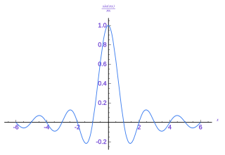
In mathematics and signal processing, the Z-transform converts a discrete-time signal, which is a sequence of real or complex numbers, into a complex valued frequency-domain representation.

In signal processing, a finite impulse response (FIR) filter is a filter whose impulse response is of finite duration, because it settles to zero in finite time. This is in contrast to infinite impulse response (IIR) filters, which may have internal feedback and may continue to respond indefinitely.

In signal processing, a periodogram is an estimate of the spectral density of a signal. The term was coined by Arthur Schuster in 1898. Today, the periodogram is a component of more sophisticated methods. It is the most common tool for examining the amplitude vs frequency characteristics of FIR filters and window functions. FFT spectrum analyzers are also implemented as a time-sequence of periodograms.

<span class="mw-page-title-main">Bandlimiting</span> Limiting a signal to contain only low-frequency components

Bandlimiting refers to a process which reduces the energy of a signal to an acceptably low level outside of a desired frequency range.

In mathematics and signal processing, the Hilbert transform is a specific singular integral that takes a function, u(t) of a real variable and produces another function of a real variable H(u)(t). The Hilbert transform is given by the Cauchy principal value of the convolution with the function (see § Definition). The Hilbert transform has a particularly simple representation in the frequency domain: It imparts a phase shift of ±90° (π/2 radians) to every frequency component of a function, the sign of the shift depending on the sign of the frequency (see § Relationship with the Fourier transform). The Hilbert transform is important in signal processing, where it is a component of the analytic representation of a real-valued signal u(t). The Hilbert transform was first introduced by David Hilbert in this setting, to solve a special case of the Riemann–Hilbert problem for analytic functions.

<span class="mw-page-title-main">Discrete wavelet transform</span> Transform in numerical harmonic analysis

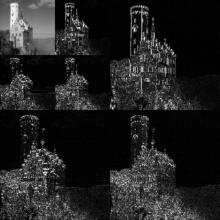
In numerical analysis and functional analysis, a discrete wavelet transform (DWT) is any wavelet transform for which the wavelets are discretely sampled. As with other wavelet transforms, a key advantage it has over Fourier transforms is temporal resolution: it captures both frequency and location information.

In signal processing, the output of the matched filter is given by correlating a known delayed signal, or template, with an unknown signal to detect the presence of the template in the unknown signal. This is equivalent to convolving the unknown signal with a conjugated time-reversed version of the template. The matched filter is the optimal linear filter for maximizing the signal-to-noise ratio (SNR) in the presence of additive stochastic noise.

In mathematics, the discrete-time Fourier transform (DTFT) is a form of Fourier analysis that is applicable to a sequence of discrete values.

<span class="mw-page-title-main">Upsampling</span>

In digital signal processing, upsampling, expansion, and interpolation are terms associated with the process of resampling in a multi-rate digital signal processing system. Upsampling can be synonymous with expansion, or it can describe an entire process of expansion and filtering (interpolation). When upsampling is performed on a sequence of samples of a signal or other continuous function, it produces an approximation of the sequence that would have been obtained by sampling the signal at a higher rate. For example, if compact disc audio at 44,100 samples/second is upsampled by a factor of 5/4, the resulting sample-rate is 55,125.

In signal processing, oversampling is the process of sampling a signal at a sampling frequency significantly higher than the Nyquist rate. Theoretically, a bandwidth-limited signal can be perfectly reconstructed if sampled at the Nyquist rate or above it. The Nyquist rate is defined as twice the bandwidth of the signal. Oversampling is capable of improving resolution and signal-to-noise ratio, and can be helpful in avoiding aliasing and phase distortion by relaxing anti-aliasing filter performance requirements.

<span class="mw-page-title-main">Linear time-invariant system</span> Mathematical model which is both linear and time-invariant

In system analysis, among other fields of study, a linear time-invariant (LTI) system is a system that produces an output signal from any input signal subject to the constraints of linearity and time-invariance; these terms are briefly defined below. These properties apply (exactly or approximately) to many important physical systems, in which case the response y(t) of the system to an arbitrary input x(t) can be found directly using convolution: y(t) = (xh)(t) where h(t) is called the system's impulse response and ∗ represents convolution (not to be confused with multiplication). What's more, there are systematic methods for solving any such system (determining h(t)), whereas systems not meeting both properties are generally more difficult (or impossible) to solve analytically. A good example of an LTI system is any electrical circuit consisting of resistors, capacitors, inductors and linear amplifiers.

<span class="mw-page-title-main">Filter bank</span> Tool for Digital Signal Processing

In signal processing, a filter bank is an array of bandpass filters that separates the input signal into multiple components, each one carrying a single frequency sub-band of the original signal. One application of a filter bank is a graphic equalizer, which can attenuate the components differently and recombine them into a modified version of the original signal. The process of decomposition performed by the filter bank is called analysis ; the output of analysis is referred to as a subband signal with as many subbands as there are filters in the filter bank. The reconstruction process is called synthesis, meaning reconstitution of a complete signal resulting from the filtering process.

Circular convolution, also known as cyclic convolution, is a special case of periodic convolution, which is the convolution of two periodic functions that have the same period. Periodic convolution arises, for example, in the context of the discrete-time Fourier transform (DTFT). In particular, the DTFT of the product of two discrete sequences is the periodic convolution of the DTFTs of the individual sequences. And each DTFT is a periodic summation of a continuous Fourier transform function. Although DTFTs are usually continuous functions of frequency, the concepts of periodic and circular convolution are also directly applicable to discrete sequences of data. In that context, circular convolution plays an important role in maximizing the efficiency of a certain kind of common filtering operation.

In mathematical analysis and applications, multidimensional transforms are used to analyze the frequency content of signals in a domain of two or more dimensions.

This article provides a short survey of the concepts, principles and applications of Multirate Filter Banks and Multidimensional Directional Filter Banks.

References

  1. Oppenheim, Alan V.; Schafer, Ronald W.; Buck, John R. (1999). "4". Discrete-Time Signal Processing (2nd ed.). Upper Saddle River, N.J.: Prentice Hall. p.  168. ISBN   0-13-754920-2.
  2. Tan, Li (2008-04-21). "Upsampling and downsampling". eetimes.com. EE Times. Retrieved 2017-04-10. The process of reducing a sampling rate by an integer factor is referred to as downsampling of a data sequence. We also refer to downsampling as decimation. The term decimation used for the downsampling process has been accepted and used in many textbooks and fields.
  3. Crochiere, R.E.; Rabiner, L.R. (1983). "2". Multirate Digital Signal Processing. Englewood Cliffs, NJ: Prentice-Hall. p. 32. ISBN   0136051626.
  4. Poularikas, Alexander D. (September 1998). Handbook of Formulas and Tables for Signal Processing (1 ed.). CRC Press. pp. 42–48. ISBN   0849385792.
  5. Harris, Frederic J. (2004-05-24). "2.2". Multirate Signal Processing for Communication Systems. Upper Saddle River, NJ: Prentice Hall PTR. pp. 20–21. ISBN   0131465112. The process of down sampling can be visualized as a two-step progression. The process starts as an input series x(n) that is processed by a filter h(n) to obtain the output sequence y(n) with reduced bandwidth. The sample rate of the output sequence is then reduced Q-to-1 to a rate commensurate with the reduced signal bandwidth. In reality the processes of bandwidth reduction and sample rate reduction are merged in a single process called a multirate filter.
  6. Strang, Gilbert; Nguyen, Truong (1996-10-01). Wavelets and Filter Banks (2 ed.). Wellesley, MA: Wellesley-Cambridge Press. pp.  100–101. ISBN   0961408871. No sensible engineer would do that.
  7. Milić, Ljiljana (2009). Multirate Filtering for Digital Signal Processing. New York: Hershey. p. 192. ISBN   978-1-60566-178-0. Generally, this approach is applicable when the ratio Fy/Fx is a rational, or an irrational number, and is suitable for the sampling rate increase and for the sampling rate decrease.

Further reading