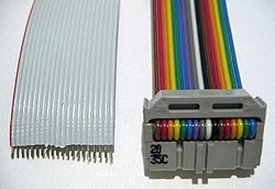
Two ribbon cables: the grey cable is stripped, and the rainbow cable has an IDC connectorConnector bladesIDC D-sub connectors DE-9 (male) and DA-15 (female)Connector blades cut insulation into the ribbon cableAustralian (dual) power outlet, utilizing insulation displacement to connect mains voltage (230 V) supply conductors
An insulation-displacement contact (IDC), also known as insulation-piercing contact (IPC), is an electrical connector designed to be connected to the conductor(s) of an insulated cable by a connection process which forces a selectively sharpened blade or blades through the insulation, bypassing the need to strip the conductors of insulation before connecting. When properly made, the connector blade cold-welds to the conductor, making a theoretically reliable gas-tight connection.[1][2]
Modern IDC technology developed after and was influenced by research on wire-wrap and crimp connector technology originally pioneered by Western Electric, Bell Telephone Labs, and others.[3] Although originally designed to connect only solid (single-stranded) conductors, IDC technology was eventually extended to multiple-stranded wire as well.
Initially, IDCs were seen only in extra-low voltage applications, such as telecommunications, networking and signal connections between parts of an electronic or computer system. However, they are now also used in some domestic and industrial low voltage (power) applications, as can be seen in the illustration.[4][5] The benefits claimed for their use in these applications include up to 50 percent faster installation, due to the reduction in the stripping, twisting and screwing down processes[citation needed].
Ribbon cable
Ribbon cable is designed to be used with multi-contact IDC connectors in such a way that many IDC connections can be made at once, saving time in applications where many connections are needed. These connectors are not designed to be reusable, but can often be re-used if care is taken when removing the cable.
Pin 1 is typically indicated on the body of the connector by a red or raised "V" mark. The corresponding wire in a ribbon cable is usually indicated by red coloration, a raised molded ridge, or markings printed onto the cable insulation. On the connector pin 2 is opposite pin 1, pin 3 is next to pin 1 along the length of the connector, and so on. On the cable, the wire connected to pin 2 is next to the wire connected to pin 1 (the red coded wire), and so on.
Telephone and network plugs
In some types of telephone and network plug, including the BS 6312 and the registered jack (RJ) family, generally separate wires in a sheath are used. In these applications, the outer sheath is stripped then the wires are inserted into the connector and a special termination tool is used to force the conductors into the contacts. Traditionally these connectors have been used with flat cable which makes it easy to ensure the correct conductors go into the correct slots. Modular connectors used with Category 5twisted pair cable require careful arranging of the conductors by hand before inserting them into the connector.
Punch-down blocks
Punch-down blocks are intended to connect individual conductors punched down into each position in the block with a special punch-down tool. Punch-down terminations are also generally seen in telephone and network connectors, in patch panels and distribution frames, and in telephone equipment such as PBXs.
Common layouts
The "V" mark (circled) shows the position of pin 1
Pins are commonly numbered from pin 1 with odd numbers along one side and the even numbers along the other side. Connectors are categorized by pin spacing in mm (pitch), number of pins, and number of rows. Connectors commonly used in computers include:
2.5 inch IDE notebook computer hard disk drives – 2.00mm pitch, 44 pins, 2×22 (2 rows of 22 pins)
SCSI 8-bit – 2.54 mm pitch, 50 pins, 2×25 (2 rows of 25 pins)
SCSI 16-bit – 1.27 mm pitch, 68 pins, 2×34 (2 rows of 34 pins)
Floppy disk – 2.54 mm pitch, 34 pins, 2×17 (2 rows of 17 pins)[6]
SerialDE-9 on motherboards – 2.54 mm pitch, 10 pins, 2×5 (2 rows of 5 pins) – sometimes called everex[7]
ParallelDB-25 – 2.54 mm pitch, 26 pins, 2×13 (2 rows of 13 pins)[8]
In some instances USB through version 2 on motherboards – 2.54 mm pitch, 10 pins, 2×5 (2 rows of 5 pins)[9]
For all of the above connectors, the computer manufacturer typically attaches a female IDC connector onto one end of a ribbon cable, and later slides that connector onto a matching male box header or pin header on the computer motherboard.
This page is based on this Wikipedia article Text is available under the CC BY-SA 4.0 license; additional terms may apply. Images, videos and audio are available under their respective licenses.