An electromagnetic coil is an electrical conductor such as a wire in the shape of a coil. Electromagnetic coils are used in electrical engineering, in applications where electric currents interact with magnetic fields, in devices such as electric motors, generators, inductors, electromagnets, transformers, sensor coils such as in medical MRI imaging machines. Either an electric current is passed through the wire of the coil to generate a magnetic field, or conversely, an external time-varying magnetic field through the interior of the coil generates an EMF (voltage) in the conductor.

An inductor, also called a coil, choke, or reactor, is a passive two-terminal electrical component that stores energy in a magnetic field when electric current flows through it. An inductor typically consists of an insulated wire wound into a coil.

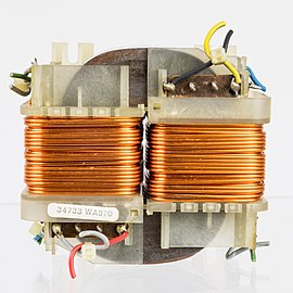
In electrical engineering, a transformer is a passive component that transfers electrical energy from one electrical circuit to another circuit, or multiple circuits. A varying current in any coil of the transformer produces a varying magnetic flux in the transformer's core, which induces a varying electromotive force (EMF) across any other coils wound around the same core. Electrical energy can be transferred between separate coils without a metallic (conductive) connection between the two circuits. Faraday's law of induction, discovered in 1831, describes the induced voltage effect in any coil due to a changing magnetic flux encircled by the coil.

A Tesla coil is an electrical resonant transformer circuit designed by inventor Nikola Tesla in 1891. It is used to produce high-voltage, low-current, high-frequency alternating-current electricity. Tesla experimented with a number of different configurations consisting of two, or sometimes three, coupled resonant electric circuits.

Electromagnetic or magnetic induction is the production of an electromotive force (emf) across an electrical conductor in a changing magnetic field.

Inductance is the tendency of an electrical conductor to oppose a change in the electric current flowing through it. The electric current produces a magnetic field around the conductor. The magnetic field strength depends on the magnitude of the electric current, and follows any changes in the magnitude of the current. From Faraday's law of induction, any change in magnetic field through a circuit induces an electromotive force (EMF) (voltage) in the conductors, a process known as electromagnetic induction. This induced voltage created by the changing current has the effect of opposing the change in current. This is stated by Lenz's law, and the voltage is called back EMF.

A balun is an electrical device that allows balanced and unbalanced lines to be interfaced without disturbing the impedance arrangement of either line. A balun can take many forms and may include devices that also transform impedances but need not do so. Sometimes, in the case of transformer baluns, they use magnetic coupling but need not do so. Common-mode chokes are also used as baluns and work by eliminating, rather than rejecting, common mode signals.
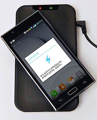
Wireless power transfer (WPT), wireless power transmission, wireless energy transmission (WET), or electromagnetic power transfer is the transmission of electrical energy without wires as a physical link. In a wireless power transmission system, an electrically powered transmitter device generates a time-varying electromagnetic field that transmits power across space to a receiver device; the receiver device extracts power from the field and supplies it to an electrical load. The technology of wireless power transmission can eliminate the use of the wires and batteries, thereby increasing the mobility, convenience, and safety of an electronic device for all users. Wireless power transfer is useful to power electrical devices where interconnecting wires are inconvenient, hazardous, or are not possible.

An isolation transformer is a transformer used to transfer electrical power from a source of alternating current (AC) power to some equipment or device while isolating the powered device from the power source, usually for safety reasons or to reduce transients and harmonics. Isolation transformers provide galvanic isolation; no conductive path is present between source and load. This isolation is used to protect against electric shock, to suppress electrical noise in sensitive devices, or to transfer power between two circuits which must not be connected. A transformer sold for isolation is often built with special insulation between primary and secondary, and is specified to withstand a high voltage between windings.
In an electrical system, a ground loop or earth loop occurs when two points of a circuit are intended to have the same ground reference potential but instead have a different potential between them. This is typically caused when enough current is flowing in the connection between the two ground points to produce a voltage drop and cause two points to be at different potentials. Current may be produced in a circular ground connection by electromagnetic induction.

A spark-gap transmitter is an obsolete type of radio transmitter which generates radio waves by means of an electric spark. Spark-gap transmitters were the first type of radio transmitter, and were the main type used during the wireless telegraphy or "spark" era, the first three decades of radio, from 1887 to the end of World War I. German physicist Heinrich Hertz built the first experimental spark-gap transmitters in 1887, with which he proved the existence of radio waves and studied their properties.

A current transformer (CT) is a type of transformer that is used to reduce or multiply an alternating current (AC). It produces a current in its secondary which is proportional to the current in its primary.
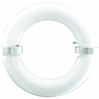
The induction lamp, electrodeless lamp, or electrodeless induction lamp is a gas-discharge lamp in which an electric or magnetic field transfers the power required to generate light from outside the lamp envelope to the gas inside. This is in contrast to a typical gas discharge lamp that uses internal electrodes connected to the power supply by conductors that pass through the lamp envelope. Eliminating the internal electrodes provides two advantages:

A loop antenna is a radio antenna consisting of a loop or coil of wire, tubing, or other electrical conductor, that for transmitting is usually fed by a balanced power source or for receiving feeds a balanced load. Within this physical description there are two distinct types:
In electronics, electric power and telecommunication, coupling is the transfer of electrical energy from one circuit to another, or between parts of a circuit. Coupling can be deliberate as part of the function of the circuit, or it may be undesirable, for instance due to coupling to stray fields. For example, energy is transferred from a power source to an electrical load by means of conductive coupling, which may be either resistive or direct coupling. An AC potential may be transferred from one circuit segment to another having a DC potential by use of a capacitor. Electrical energy may be transferred from one circuit segment to another segment with different impedance by use of a transformer; this is known as impedance matching. These are examples of electrostatic and electrodynamic inductive coupling.

An AC motor is an electric motor driven by an alternating current (AC). The AC motor commonly consists of two basic parts, an outside stator having coils supplied with alternating current to produce a rotating magnetic field, and an inside rotor attached to the output shaft producing a second rotating magnetic field. The rotor magnetic field may be produced by permanent magnets, reluctance saliency, or DC or AC electrical windings.
An inductive sensor is a device that uses the principle of electromagnetic induction to detect or measure objects. An inductor develops a magnetic field when an electric current flows through it; alternatively, a current will flow through a circuit containing an inductor when the magnetic field through it changes. This effect can be used to detect metallic objects that interact with a magnetic field. Non-metallic substances, such as liquids or some kinds of dirt, do not interact with the magnetic field, so an inductive sensor can operate in wet or dirty conditions.

Various types of electrical transformer are made for different purposes. Despite their design differences, the various types employ the same basic principle as discovered in 1831 by Michael Faraday, and share several key functional parts.

Resonant inductive coupling or magnetic phase synchronous coupling is a phenomenon with inductive coupling in which the coupling becomes stronger when the "secondary" (load-bearing) side of the loosely coupled coil resonates. A resonant transformer of this type is often used in analog circuitry as a bandpass filter. Resonant inductive coupling is also used in wireless power systems for portable computers, phones, and vehicles.
This glossary of electrical and electronics engineering is a list of definitions of terms and concepts related specifically to electrical engineering and electronics engineering. For terms related to engineering in general, see Glossary of engineering.