Op amp integrator

Last updated

The operational amplifier integrator is an electronic integration circuit. Based on the operational amplifier (op-amp), it performs the mathematical operation of integration with respect to time; that is, its output voltage is proportional to the input voltage integrated over time.

Contents

Applications

The integrator circuit is mostly used in analog computers, analog-to-digital converters and wave-shaping circuits. A common wave-shaping use is as a charge amplifier and they are usually constructed using an operational amplifier though they can use high gain discrete transistor configurations.

Design

The input current is offset by a negative feedback current flowing in the capacitor, which is generated by an increase in output voltage of the amplifier. The output voltage is therefore dependent on the value of input current it has to offset and the inverse of the value of the feedback capacitor. The greater the capacitor value, the less output voltage has to be generated to produce a particular feedback current flow.

The input capacitance of the circuit is almost zero because of the Miller effect. This ensures that the stray capacitances (the cable capacitance, the amplifier input capacitance, etc.) are virtually grounded and have no influence on the output signal. [1]

Ideal circuit

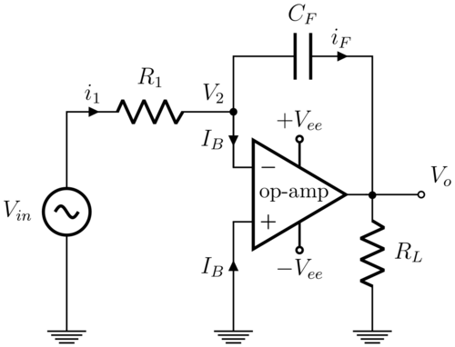
This circuit operates by passing a current that charges or discharges the capacitor during the time under consideration, which strives to retain the virtual ground condition at the input by off-setting the effect of the input current:
Integrator circuit.png

Referring to the above diagram, if the op-amp is assumed to be ideal, then the voltage at the inverting (-) input is held equal to the voltage at the non-inverting (+) input as a virtual ground. The input voltage passes a current through the resistor producing a compensating current flow through the series capacitor to maintain the virtual ground. This charges or discharges the capacitor over time. Because the resistor and capacitor are connected to a virtual ground, the input current does not vary with capacitor charge, so a linear integration that works across all frequencies is achieved (unlike RC circuit § Integrator).

The circuit can be analyzed by applying Kirchhoff's current law at the inverting input:

For an ideal op-amp, amps, so:

Furthermore, the capacitor has a voltage-current relationship governed by the equation:

Substituting the appropriate variables:

For an ideal op-amp, volts, so:

Integrating both sides with respect to time:

If the initial value of is assumed to be 0 volts, the output voltage will simply be proportional to the integral of the input voltage: [2]

Practical circuit

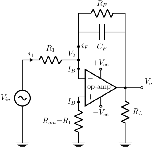
This practical integrator attempts to address a number of flaws of the ideal integrator circuit:
Practical integrator.png

Real op-amps have a finite open-loop gain, an input offset voltage and input bias currents , which may not be well-matched and may be distinguished as going into the inverting input and going into the non-inverting input. This can cause several issues for the ideal design; most importantly, if , both the output offset voltage and the input bias current can cause current to pass through the capacitor, causing the output voltage to drift over time until the op-amp saturates. Similarly, if were a signal centered about zero volts (i.e. without a DC component), no drift would be expected in an ideal circuit, but may occur in a real circuit.

To negate the effect of the input bias current, it is necessary for the non-inverting terminal to include a resistor which simplifies to provided that is much smaller than the load resistance and the feedback resistance . Well-matched input bias currents then cause the same voltage drop of at both the inverting and non-inverting terminals, to effectively cancel out the effect of bias current at those inputs.

Also, in a DC steady state, an ideal capacitor acts as an open circuit. The DC gain of the ideal circuit is therefore infinite (or in practice, the open-loop gain of a non-ideal op-amp). Any DC (or very low frequency) component may then cause the op amp output to drift into saturation. [3] To prevent this, the DC gain can be limited to a finite value by inserting a large resistor in parallel with the feedback capacitor. Note that some op amps have a large internal feedback resistor, and many real capacitors have leakage that is effectively a large feedback resistor. [4]

The addition of these resistors turns the output drift into a finite, preferably small, DC error voltage:

Notes on offset: a variation of this circuit simply uses an adjustable voltage source instead of and some op amps with very low offset voltage may not even require offset correction. [5] Offset correction is a bigger concern for older op amps, particularly BJT types. Another variation circuit to avoid offset correction that works for AC signals only is to capacitively-couple the input with large input capacitor before which will naturally charge up to the offset voltage. Additionally, because offset may drift over time and temperature, some op amps provide null offset pins, which can be connected to a potentiometer whose wiper connects to the negative supply to allow readjusting when conditions change. These methods may be combined for greater ensurance. [4]

Frequency response

Both the ideal and practical integrator have a gain of 1 at a single frequency called the unity gain frequency :

But the overall frequency response of the two circuits differ due to their different pole locations.

Ideal integrator

The ideal integrator's transfer function corresponds to the time-domain integration property of the Laplace transform. Since its denominator is just , the transfer function has a pole frequency at . Thus its frequency response has a steady -20 dB per decade slope across all frequencies and appears as a downward-sloping line in a Bode plot.

Practical integrator

The practical integrator's feedback resistor in parallel with the feedback capacitor turns the circuit into an active low-pass filter with a pole at the -3 dB cutoff frequency:

The frequency response has a relatively constant gain up to , and then decreases by 20 dB per decade. While this circuit is no longer an integrator for low frequencies around and below , the error is decreases to only 0.5% at one decade above and the response approaches that of an ideal integrator as the frequency increases. [3] Real op amps also have a limited gain-bandwidth product (GBWP), which adds an additional high frequency pole. Integration only occurs along the -20 dB per decade slope, which is steady only from frequencies about a decade above to about a decade below the op amp's GBWP. [5]

Related Research Articles

<span class="mw-page-title-main">Multivibrator</span> Electronic circuit used to implement two-state devices

A multivibrator is an electronic circuit used to implement a variety of simple two-state devices such as relaxation oscillators, timers, latches and flip-flops. The first multivibrator circuit, the astable multivibrator oscillator, was invented by Henri Abraham and Eugene Bloch during World War I. It consisted of two vacuum tube amplifiers cross-coupled by a resistor-capacitor network. They called their circuit a "multivibrator" because its output waveform was rich in harmonics. A variety of active devices can be used to implement multivibrators that produce similar harmonic-rich wave forms; these include transistors, neon lamps, tunnel diodes and others. Although cross-coupled devices are a common form, single-element multivibrator oscillators are also common.

<span class="mw-page-title-main">Operational amplifier</span> High-gain voltage amplifier with a differential input

An operational amplifier is a DC-coupled electronic voltage amplifier with a differential input, a (usually) single-ended output, and an extremely high gain. Its name comes from its original use of performing mathematical operations in analog computers.

A low-pass filter is a filter that passes signals with a frequency lower than a selected cutoff frequency and attenuates signals with frequencies higher than the cutoff frequency. The exact frequency response of the filter depends on the filter design. The filter is sometimes called a high-cut filter, or treble-cut filter in audio applications. A low-pass filter is the complement of a high-pass filter.

<span class="mw-page-title-main">Negative-feedback amplifier</span> Type of electronic amplifier

A negative-feedback amplifier is an electronic amplifier that subtracts a fraction of its output from its input, so that negative feedback opposes the original signal. The applied negative feedback can improve its performance and reduces sensitivity to parameter variations due to manufacturing or environment. Because of these advantages, many amplifiers and control systems use negative feedback.

<span class="mw-page-title-main">Instrumentation amplifier</span> Electronic amplifier, a circuit component

An instrumentation amplifier is a type of differential amplifier that has been outfitted with input buffer amplifiers, which eliminate the need for input impedance matching and thus make the amplifier particularly suitable for use in measurement and test equipment. Additional characteristics include very low DC offset, low drift, low noise, very high open-loop gain, very high common-mode rejection ratio, and very high input impedances. Instrumentation amplifiers are used where great accuracy and stability of the circuit both short- and long-term are required.

<span class="mw-page-title-main">Differential amplifier</span> Electrical circuit component which amplifies the difference of two analog signals

A differential amplifier is a type of electronic amplifier that amplifies the difference between two input voltages but suppresses any voltage common to the two inputs. It is an analog circuit with two inputs and and one output , in which the output is ideally proportional to the difference between the two voltages:

<span class="mw-page-title-main">Buffer amplifier</span> Electronic amplifier, a circuit component

In electronics, a buffer amplifier is a unity gain amplifier that copies a signal from one circuit to another while transforming its electrical impedance to provide a more ideal source. This "buffers" the signal source in the first circuit against being affected by currents from the electrical load of the second circuit and may simply be called a buffer or follower when context is clear.

<span class="mw-page-title-main">Current source</span> Electronic component delivering stable electric current regardless of voltage

A current source is an electronic circuit that delivers or absorbs an electric current which is independent of the voltage across it.

An integrator in measurement and control applications is an element whose output signal is the time integral of its input signal. It accumulates the input quantity over a defined time to produce a representative output.

Linear electronic oscillator circuits, which generate a sinusoidal output signal, are composed of an amplifier and a frequency selective element, a filter. A linear oscillator circuit which uses an RC network, a combination of resistors and capacitors, for its frequency selective part is called an RC oscillator.

The open-loop gain of an electronic amplifier is the gain obtained when no overall feedback is used in the circuit.

This article illustrates some typical operational amplifier applications. A non-ideal operational amplifier's equivalent circuit has a finite input impedance, a non-zero output impedance, and a finite gain. A real op-amp has a number of non-ideal features as shown in the diagram, but here a simplified schematic notation is used, many details such as device selection and power supply connections are not shown. Operational amplifiers are optimised for use with negative feedback, and this article discusses only negative-feedback applications. When positive feedback is required, a comparator is usually more appropriate. See Comparator applications for further information.

<span class="mw-page-title-main">Current divider</span> Simple linear circuit

In electronics, a current divider is a simple linear circuit that produces an output current (IX) that is a fraction of its input current (IT). Current division refers to the splitting of current between the branches of the divider. The currents in the various branches of such a circuit will always divide in such a way as to minimize the total energy expended.

A phase-shift oscillator is a linear electronic oscillator circuit that produces a sine wave output. It consists of an inverting amplifier element such as a transistor or op amp with its output fed back to its input through a phase-shift network consisting of resistors and capacitors in a ladder network. The feedback network 'shifts' the phase of the amplifier output by 180 degrees at the oscillation frequency to give positive feedback. Phase-shift oscillators are often used at audio frequency as audio oscillators.

<span class="mw-page-title-main">Parasitic capacitance</span> Usually unwanted capacitance in a circuit

Parasitic capacitance or stray capacitance is the unavoidable and usually unwanted capacitance that exists between the parts of an electronic component or circuit simply because of their proximity to each other. When two electrical conductors at different voltages are close together, the electric field between them causes electric charge to be stored on them; this effect is capacitance.

A switched capacitor (SC) is an electronic circuit that implements a function by moving charges into and out of capacitors when electronic switches are opened and closed. Usually, non-overlapping clock signals are used to control the switches, so that not all switches are closed simultaneously. Filters implemented with these elements are termed switched-capacitor filters, which depend only on the ratios between capacitances and the switching frequency, and not on precise resistors. This makes them much more suitable for use within integrated circuits, where accurately specified resistors and capacitors are not economical to construct, but accurate clocks and accurate relative ratios of capacitances are economical.

In electronics, a differentiator is a circuit that outputs a signal approximately proportional to the rate of change of its input signal. Because the derivative of a sinusoid in another sinusoid whose amplitude is multiplied by its frequency, a true differentiator that works across all frequencies can't be realized. Real circuits such as a 1st-order high-pass filter are able to approximate differentiation at lower frequencies by limiting the gain above its cutoff frequency. An active differentiator includes an amplifier, while a passive differentiator is made only of resistors, capacitors and inductors.

An integrating ADC is a type of analog-to-digital converter that converts an unknown input voltage into a digital representation through the use of an integrator. In its basic implementation, the dual-slope converter, the unknown input voltage is applied to the input of the integrator and allowed to ramp for a fixed time period. Then a known reference voltage of opposite polarity is applied to the integrator and is allowed to ramp until the integrator output returns to zero. The input voltage is computed as a function of the reference voltage, the constant run-up time period, and the measured run-down time period. The run-down time measurement is usually made in units of the converter's clock, so longer integration times allow for higher resolutions. Likewise, the speed of the converter can be improved by sacrificing resolution.

The Miller theorem refers to the process of creating equivalent circuits. It asserts that a floating impedance element, supplied by two voltage sources connected in series, may be split into two grounded elements with corresponding impedances. There is also a dual Miller theorem with regards to impedance supplied by two current sources connected in parallel. The two versions are based on the two Kirchhoff's circuit laws.

<span class="mw-page-title-main">Transimpedance amplifier</span> Amplifier that converts current to voltage

In electronics, a transimpedance amplifier (TIA) is a current to voltage converter, almost exclusively implemented with one or more operational amplifiers. The TIA can be used to amplify the current output of Geiger–Müller tubes, photo multiplier tubes, accelerometers, photo detectors and other types of sensors to a usable voltage. Current to voltage converters are used with sensors that have a current response that is more linear than the voltage response. This is the case with photodiodes where it is not uncommon for the current response to have better than 1% nonlinearity over a wide range of light input. The transimpedance amplifier presents a low impedance to the photodiode and isolates it from the output voltage of the operational amplifier. In its simplest form a transimpedance amplifier has just a large valued feedback resistor, Rf. The gain of the amplifier is set by this resistor and because the amplifier is in an inverting configuration, has a value of -Rf. There are several different configurations of transimpedance amplifiers, each suited to a particular application. The one factor they all have in common is the requirement to convert the low-level current of a sensor to a voltage. The gain, bandwidth, as well as current and voltage offsets change with different types of sensors, requiring different configurations of transimpedance amplifiers.

References

  1. Transducers with Charge Output
  2. "AN1177 Op Amp Precision Design: DC Errors" (PDF). Microchip. 2 January 2008. Archived (PDF) from the original on 2019-07-09. Retrieved 26 December 2012.
  3. 1 2 Stata, Ray (1967). "Operational Integrators" (PDF). Analog Dialogue . pp. 10–11. Archived (PDF) from the original on 2020-11-12. Retrieved 2024-02-16.
  4. 1 2 Pavlic, Theodore (2009) [2007]. "Practical Integrators and Operational Amplifier Offset - Practical Integrators and Operational Amplifier Offset - ECE 327: Electronic Devices and Circuits Laboratory I" (PDF). Archived (PDF) from the original on 2022-10-11. Retrieved 2023-08-20.
  5. 1 2 "Analog Engineer's Circuit: Amplifiers - SBOA275A" (PDF). Texas Instruments . 2019 [2018]. Archived (PDF) from the original on 2022-09-01. Retrieved 2023-08-20.