Related Research Articles
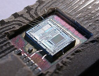
A microcontroller is a small computer on a single VLSI integrated circuit (IC) chip. A microcontroller contains one or more CPUs along with memory and programmable input/output peripherals. Program memory in the form of ferroelectric RAM, NOR flash or OTP ROM is also often included on chip, as well as a small amount of RAM. Microcontrollers are designed for embedded applications, in contrast to the microprocessors used in personal computers or other general purpose applications consisting of various discrete chips.
In computer engineering, a hardware description language (HDL) is a specialized computer language used to describe the structure and behavior of electronic circuits, and most commonly, digital logic circuits.
SPICE is a general-purpose, open-source analog electronic circuit simulator. It is a program used in integrated circuit and board-level design to check the integrity of circuit designs and to predict circuit behavior.
A mixed-signal integrated circuit is any integrated circuit that has both analog circuits and digital circuits on a single semiconductor die. Their usage has grown dramatically with the increased use of cell phones, telecommunications, portable electronics, and automobiles with electronics and digital sensors.

OrCAD Systems Corporation was a software company that made OrCAD, a proprietary software tool suite used primarily for electronic design automation (EDA). The software is used mainly by electronic design engineers and electronic technicians to create electronic schematics, and perform mixed-signal simulation and electronic prints for manufacturing printed circuit boards (PCBs). OrCAD was taken over by Cadence Design Systems in 1999 and was integrated with Cadence Allegro in 2005.

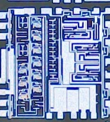
Integrated circuit design, or IC design, is a sub-field of electronics engineering, encompassing the particular logic and circuit design techniques required to design integrated circuits, or ICs. ICs consist of miniaturized electronic components built into an electrical network on a monolithic semiconductor substrate by photolithography.
Quite Universal Circuit Simulator (Qucs) is a free-software electronics circuit simulator software application released under GPL. It offers the ability to set up a circuit with a graphical user interface and simulate the large-signal, small-signal and noise behaviour of the circuit. Pure digital simulations are also supported using VHDL and/or Verilog.

NI Multisim is an electronic schematic capture and simulation program which is part of a suite of circuit design programs, along with NI Ultiboard. Multisim is one of the few circuit design programs to employ the original Berkeley SPICE based software simulation. Multisim was originally created by a company named Electronics Workbench Group, which is now a division of National Instruments. Multisim includes microcontroller simulation, as well as integrated import and export features to the printed circuit board layout software in the suite, NI Ultiboard.
Verilog-AMS is a derivative of the Verilog hardware description language that includes analog and mixed-signal extensions (AMS) in order to define the behavior of analog and mixed-signal systems. It extends the event-based simulator loops of Verilog/SystemVerilog/VHDL, by a continuous-time simulator, which solves the differential equations in analog-domain. Both domains are coupled: analog events can trigger digital actions and vice versa.
Electronic circuit design comprises the analysis and synthesis of electronic circuits.
Flow to HDL tools and methods convert flow-based system design into a hardware description language (HDL) such as VHDL or Verilog. Typically this is a method of creating designs for field-programmable gate array, application-specific integrated circuit prototyping and digital signal processing (DSP) design. Flow-based system design is well-suited to field-programmable gate array design as it is easier to specify the innate parallelism of the architecture.

Electronic circuit simulation uses mathematical models to replicate the behavior of an actual electronic device or circuit. Simulation software allows for modeling of circuit operation and is an invaluable analysis tool. Due to its highly accurate modeling capability, many colleges and universities use this type of software for the teaching of electronics technician and electronics engineering programs. Electronics simulation software engages its users by integrating them into the learning experience. These kinds of interactions actively engage learners to analyze, synthesize, organize, and evaluate content and result in learners constructing their own knowledge.
VHDL-AMS is a derivative of the hardware description language VHDL. It includes analog and mixed-signal extensions (AMS) in order to define the behavior of analog and mixed-signal systems.
Spectre is a SPICE-class circuit simulator owned and distributed by the software company Cadence Design Systems. It provides the basic SPICE analyses and component models. It also supports the Verilog-A modeling language. Spectre comes in enhanced versions that also support RF simulation (SpectreRF) and mixed-signal simulation.
Analog verification is a methodology for performing functional verification on analog, mixed-signal and RF integrated circuits and systems on chip. Discussion of analog verification began in 2005 when it started to become recognized that the analog portion of large mixed-signal chips had become so complex that a significant and ever-increasing number of these chips were being designed with functional errors in the analog portion that prevented them from operating correctly.
This page is a comparison of electronic design automation (EDA) software which is used today to design the near totality of electronic devices. Modern electronic devices are too complex to be designed without the help of a computer. Electronic devices may consist of integrated circuits (ICs), printed circuit boards (PCBs), field programmable gate arrays (FPGAs) or a combination of them. Integrated circuits may consist of a combination of digital and analog circuits. These circuits can contain a combination of transistors, resistors, capacitors or specialized components such as analog neural networks, antennas or fuses.
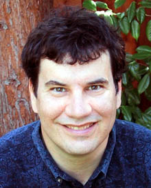
Kenneth S. Kundert is an engineer that is notable for his work in the area of Electronic Design Automation (EDA). He studied electrical engineering at the University of California, Berkeley under professors Alberto Sangiovanni-Vincentelli and Robert G. Meyer and received his doctorate in 1989. During this time, he created the circuit simulator that eventually became the Advanced Design System from what is now PathWave Design and the Spectre circuit simulator from Cadence Design Systems.
PSIM is an Electronic circuit simulation software package, designed specifically for use in power electronics and motor drive simulations but can be used to simulate any electronic circuit. Developed by Powersim, PSIM uses nodal analysis and the trapezoidal rule integration as the basis of its simulation algorithm. PSIM provides a schematic capture interface and a waveform viewer Simview. PSIM has several modules that extend its functionality into specific areas of circuit simulation and design including: control theory, electric motors, photovoltaics and wind turbines PSIM is used by industry for research and product development and it is used by educational institutions for research and teaching and was acquired by Altair Engineering in March 2022.
The Proteus Design Suite is a proprietary software tool suite used primarily for electronic design automation. The software is used mainly by electronic design engineers and technicians to create schematics and electronic prints for manufacturing printed circuit boards.
References
- ↑ Walczowski, Les T. and Dimond, Keith R. and Waller, Winston A.J. "A digital engineering curriculum for the new millennium" International Journal of Electrical Engineering Education 37 (1), 2000, pp. 108-117. ISSN 0020-7209.
- 1 2 3 4 5 Dogan Ibrahim."Teaching microcontroller programming using “TINA” simulation" AWER Procedia Information Technology Computer Science 1, 2012 pp. 42-47.
- ↑ Clive Ousbey."Design Lab bytes" Electronics World, Sept. 1996 pp.663-665.
- ↑ TINA release history
- ↑ Don Tuite."Free Downloadable Spice Tools Capture And Simulate Analog Circuits" Electronic Design Oct 23, 2012
- 1 2 John Rice."Accelerating Power-Supply Compliance to Specification" Texas Instruments, Power Supply Design Seminar, SEM2000, Topic 6, 2013
- ↑ Thomas R. Salvatierra."Design and Evaluation of an audio-frequency transresistance amplifier for magnetic tape playback" Wright State University, 2011, pp.69-73.
- ↑ John Rice."Protect an LED driver against output short to ground" LEDs Magazine, February, 2015, pp.69-71.
- ↑ Jack Browne."Simulation Tools Build On Electromagnetic Analysis" MicroWaves&RF, Jun 16, 2006
- ↑ "E-blocks: Accelerated Design: E-blocks+Flowcode+TINA" Elector Magazin, September, 2008, p.68.
- ↑ Paul Rako."Spice simulation, Tina-TI, LTSpice, PSpice, and more" EDN Network, May 06, 2011
- ↑ Hegyesi, F."Education of electronics in University by TINACloud" Intelligent Systems and Informatics (SISY), 2013 IEEE 11th International Symposium, 26-28 Sept. 2013, pp.385-389.
- ↑ Graham Prophet."Online prototyping with A/D simulation, in Infineon Designer" EETimes Europe, October 31, 2016
- ↑ Worlddidac Award 2006
- ↑ Worlddidac Award 2014