
An electrical network is an interconnection of electrical components or a model of such an interconnection, consisting of electrical elements. An electrical circuit is a network consisting of a closed loop, giving a return path for the current. Thus all circuits are networks, but not all networks are circuits.
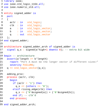
VHDL is a hardware description language that can model the behavior and structure of digital systems at multiple levels of abstraction, ranging from the system level down to that of logic gates, for design entry, documentation, and verification purposes. The language was developed for the US military VHSIC program in the 1980s, and has been standardized by the Institute of Electrical and Electronics Engineers (IEEE) as IEEE Std 1076; the latest version of which is IEEE Std 1076-2019. To model analog and mixed-signal systems, an IEEE-standardized HDL based on VHDL called VHDL-AMS has been developed.
Verilog, standardized as IEEE 1364, is a hardware description language (HDL) used to model electronic systems. It is most commonly used in the design and verification of digital circuits, with the highest level of abstraction being at the register-transfer level. It is also used in the verification of analog circuits and mixed-signal circuits, as well as in the design of genetic circuits. In 2009, the Verilog standard was merged into the SystemVerilog standard, creating IEEE Standard 1800-2009. Since then, Verilog has been officially part of the SystemVerilog language. The current version is IEEE standard 1800-2023.

Accellera Systems Initiative (Accellera) is a standards organization that supports a mix of user and vendor standards and open interfaces development in the area of electronic design automation (EDA) and integrated circuit (IC) design and manufacturing. It is less constrained than the Institute of Electrical and Electronics Engineers (IEEE) and is therefore the starting place for many standards. Once mature and adopted by the broader community, the standards are usually transferred to the IEEE.
SystemC is a set of C++ classes and macros which provide an event-driven simulation interface. These facilities enable a designer to simulate concurrent processes, each described using plain C++ syntax. SystemC processes can communicate in a simulated real-time environment, using signals of all the datatypes offered by C++, some additional ones offered by the SystemC library, as well as user defined. In certain respects, SystemC deliberately mimics the hardware description languages VHDL and Verilog, but is more aptly described as a system-level modeling language.
SystemVerilog, standardized as IEEE 1800, is a hardware description and hardware verification language used to model, design, simulate, test and implement electronic systems. SystemVerilog is based on Verilog and some extensions, and since 2008, Verilog is now part of the same IEEE standard. It is commonly used in the semiconductor and electronic design industry as an evolution of Verilog.
Ngspice is an open-source mixed-level/mixed-signal electronic circuit simulator. It is a successor of the latest stable release of Berkeley SPICE, version 3f.5, which was released in 1993. A small group of maintainers and the user community contribute to the ngspice project by providing new features, enhancements and bug fixes.

Quite Universal Circuit Simulator (Qucs) is a free-software electronics circuit simulator software application released under GPL. It offers the ability to set up a circuit with a graphical user interface and simulate the large-signal, small-signal and noise behaviour of the circuit. Pure digital simulations are also supported using VHDL and/or Verilog. Only a small set of digital devices like flip flops and logic gates can be used with analog circuits. Qucs uses its own SPICE-incompatible backend simulator Qucsator, however the Qucs-S fork supports some SPICE backends.
Verilog-AMS is a derivative of the Verilog hardware description language that includes Analog and Mixed-Signal extensions (AMS) in order to define the behavior of analog and mixed-signal systems. It extends the event-based simulator loops of Verilog/SystemVerilog/VHDL, by a continuous-time simulator, which solves the differential equations in analog-domain. Both domains are coupled: analog events can trigger digital actions and vice versa.
Electronic circuit design comprises the analysis and synthesis of electronic circuits.
Flow to HDL tools and methods convert flow-based system design into a hardware description language (HDL) such as VHDL or Verilog. Typically this is a method of creating designs for field-programmable gate array, application-specific integrated circuit prototyping and digital signal processing (DSP) design. Flow-based system design is well-suited to field-programmable gate array design as it is easier to specify the innate parallelism of the architecture.

Electronic circuit simulation uses mathematical models to replicate the behavior of an actual electronic device or circuit. Simulation software allows for the modeling of circuit operation and is an invaluable analysis tool. Due to its highly accurate modeling capability, many colleges and universities use this type of software for the teaching of electronics technician and electronics engineering programs. Electronics simulation software engages its users by integrating them into the learning experience. These kinds of interactions actively engage learners to analyze, synthesize, organize, and evaluate content and result in learners constructing their own knowledge.
Open Verification Library (OVL) is a library of property checkers for digital circuit descriptions written in popular Hardware Description Languages (HDLs). OVL is currently maintained by Accellera.
The Design Automation Standards Committee (DASC) is a subgroup of interested individuals members of the Institute of Electrical and Electronics Engineers (IEEE) Computer Society and Standards Association. It oversees IEEE Standards that are related to computer-aided design. It is part of the IEEE Computer Society.
VHDL-AMS is a derivative of the hardware description language VHDL. It includes analog and mixed-signal extensions (AMS) in order to define the behavior of analog and mixed-signal systems.
SystemVerilog DPI is an interface which can be used to interface SystemVerilog with foreign languages. These foreign languages can be C, C++, SystemC as well as others. DPIs consist of two layers: a SystemVerilog layer and a foreign language layer. Both the layers are isolated from each other.
The following outline is provided as an overview of and topical guide to electronics:
Automatic Device Model Synthesizer (ADMS) is public domain software used in the semiconductor industry to translate Verilog-A models into C-models which can be directly read by a number of SPICE simulators, including Spectre Circuit Simulator, Ngspice, and HSpice.
SystemC AMS is an extension to SystemC for analog, mixed-signal and RF functionality. The SystemC AMS 2.0 standard was released on April 6, 2016 as IEEE Std 1666.1-2016.

SPICE OPUS is a free general purpose electronic circuit simulator, developed and maintained by members of EDA Group, University of Ljubljana, Slovenia. It is based on original Berkeley’s SPICE analog circuit simulator and includes various improvements and advances, such as memory-leak bug fixes and plotting tool improvements. SPICE OPUS is specially designed for fast optimization loops via its built-in optimizer.