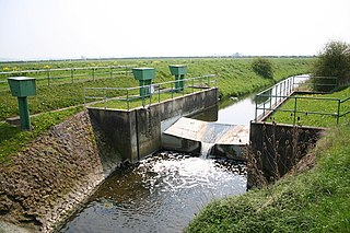
A stream gauge, streamgage or stream gauging station is a location used by hydrologists or environmental scientists to monitor and test terrestrial bodies of water. Hydrometric measurements of water level surface elevation ("stage") and/or volumetric discharge (flow) are generally taken and observations of biota and water quality may also be made. The locations of gauging stations are often found on topographical maps. Some gauging stations are highly automated and may include telemetry capability transmitted to a central data logging facility.
Flow measurement is the quantification of bulk fluid movement. Flow can be measured in a variety of ways. The common types of flowmeters with industrial applications are listed below:
In continuum mechanics, the Froude number is a dimensionless number defined as the ratio of the flow inertia to the external field. Named after William Froude, the Froude number is based on the speed–length ratio which he defined as:

In physics and engineering, in particular fluid dynamics, the volumetric flow rate is the volume of fluid which passes per unit time; usually it is represented by the symbol Q. It contrasts with mass flow rate, which is the other main type of fluid flow rate. In most contexts a mention of rate of fluid flow is likely to refer to the volumetric rate. In hydrometry, the volumetric flow rate is known as discharge.
The hydraulic diameter, DH, is a commonly used term when handling flow in non-circular tubes and channels. Using this term, one can calculate many things in the same way as for a round tube. When the cross-section is uniform along the tube or channel length, it is defined as
In hydrology, discharge is the volumetric flow rate of water that is transported through a given cross-sectional area. It includes any suspended solids, dissolved chemicals, or biologic material in addition to the water itself. Terms may vary between disciplines. For example, a fluvial hydrologist studying natural river systems may define discharge as streamflow, whereas an engineer operating a reservoir system may equate it with outflow, contrasted with inflow.
An aquifer test is conducted to evaluate an aquifer by "stimulating" the aquifer through constant pumping, and observing the aquifer's "response" (drawdown) in observation wells. Aquifer testing is a common tool that hydrogeologists use to characterize a system of aquifers, aquitards and flow system boundaries.

A culvert is a structure that channels water past an obstacle or to a subterranean waterway. Typically embedded so as to be surrounded by soil, a culvert may be made from a pipe, reinforced concrete or other material. In the United Kingdom, the word can also be used for a longer artificially buried watercourse.
In water-related science and engineering, there are two similar but distinct definitions in use for the word drawdown:
The Manning formula is an empirical formula estimating the average velocity of a liquid flowing in a conduit that does not completely enclose the liquid, i.e., open channel flow. However, this equation is also used for calculation of flow variables in case of flow in partially full conduits, as they also possess a free surface like that of open channel flow. All flow in so-called open channels is driven by gravity. It was first presented by the French engineer Philippe Gauckler in 1867, and later re-developed by the Irish engineer Robert Manning in 1890.
In fluid statics, capillary pressure is the pressure between two immiscible fluids in a thin tube, resulting from the interactions of forces between the fluids and solid walls of the tube. Capillary pressure can serve as both an opposing or driving force for fluid transport and is a significant property for research and industrial purposes. It is also observed in natural phenomena.

The shallow-water equations are a set of hyperbolic partial differential equations that describe the flow below a pressure surface in a fluid. The shallow-water equations in unidirectional form are also called Saint-Venant equations, after Adhémar Jean Claude Barré de Saint-Venant.
In hydraulic engineering, a nappe is a sheet or curtain of water that flows over a weir or dam. The upper and lower water surface have well-defined characteristics that are created by the crest of a dam or weir. Both structures have different features that characterize how a nappe might flow through or over impervious concrete structures. Hydraulic engineers distinguish these two water structures in characterizing and calculating the formation of a nappe. Engineers account for the bathymetry of standing bodies or moving bodies of water. An appropriate crest is built for the dam or weir so that dam failure is not caused by nappe vibration or air cavitation from free-overall structures.
The Chézy formula is an semi-empirical resistance equation which estimates mean flow velocity in open channel conduits. The relationship was realized and developed in 1768 by French physicist and engineer Antoine de Chézy (1718–1798) while designing Paris's water canal system. Chézy discovered a similarity parameter that could be used for estimating flow characteristics in one channel based on the measurements of another. The Chézy formula relates the flow of water through an open channel with the channel's dimensions and slope. The Chézy equation is a pioneering formula in the field of fluid mechanics and was expanded and modified by Irish Engineer Robert Manning in 1889. Manning's modifications to the Chézy formula allowed the entire similarity parameter to be calculated by channel characteristics rather than by experimental measurements. Today, the Chézy and Manning equations continue to accurately estimate open channel fluid flow and are standard formulas in all fields that relate to fluid mechanics and hydraulics, including physics, mechanical engineering and civil engineering.
The depth–slope product is used to calculate the shear stress at the bed of an open channel containing fluid that is undergoing steady, uniform flow. It is widely used in river engineering, stream restoration, sedimentology, and fluvial geomorphology. It is the product of the water depth and the mean bed slope, along with the acceleration due to gravity and density of the fluid.

The Reynolds number helps predict flow patterns in different fluid flow situations. At low Reynolds numbers, flows tend to be dominated by laminar (sheet-like) flow, while at high Reynolds numbers flows tend to be turbulent. The turbulence results from differences in the fluid's speed and direction, which may sometimes intersect or even move counter to the overall direction of the flow. These eddy currents begin to churn the flow, using up energy in the process, which for liquids increases the chances of cavitation. Reynolds numbers are an important dimensionless quantity in fluid mechanics.
In physics, a characteristic length is an important dimension that defines the scale of a physical system. Often, such a length is used as an input to a formula in order to predict some characteristics of the system, and it is usually required by the construction of a dimensionless quantity, in the general framework of dimensional analysis and in particular applications such as fluid mechanics.
A common open channel flow problem is determining the discharge from a lake to a rectangular channel.
In fluid dynamics, the entrance length is the distance a flow travels after entering a pipe before the flow becomes fully developed. Entrance length refers to the length of the entry region, the area following the pipe entrance where effects originating from the interior wall of the pipe propagate into the flow as an expanding boundary layer. When the boundary layer expands to fill the entire pipe, the developing flow becomes a fully developed flow, where flow characteristics no longer change with increased distance along the pipe. Many different entrance lengths exist to describe a variety of flow conditions. Hydrodynamic entrance length describes the formation of a velocity profile caused by viscous forces propagating from the pipe wall. Thermal entrance length describes the formation of a temperature profile. Awareness of entrance length may be necessary for the effective placement of instrumentation, such as fluid flow meters.
This article is about flow in partially full conduits.


