Desargues configuration

Last updated
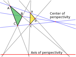
Two perspective triangles, and their center and axis of perspectivity Desargues theorem alt.svg
Two perspective triangles, and their center and axis of perspectivity

In geometry, the Desargues configuration is a configuration of ten points and ten lines, with three points per line and three lines per point. It is named after Girard Desargues.

Contents

The Desargues configuration can be constructed in two dimensions from the points and lines occurring in Desargues's theorem, in three dimensions from five planes in general position, or in four dimensions from the 5-cell, the four-dimensional regular simplex. It has a large group of symmetries, taking any point to any other point and any line to any other line. It is also self-dual, meaning that if the points are replaced by lines and vice versa using projective duality, the same configuration results.

Graphs associated with the Desargues configuration include the Desargues graph (its graph of point-line incidences) and the Petersen graph (its graph of non-incident lines). The Desargues configuration is one of ten different configurations with ten points and lines, three points per line, and three lines per point, nine of which can be realized in the Euclidean plane.

Constructions

A two-dimensional realization of the Desargues configuration from Saniga, Holweck & Pracna (2015) Desargues configuration g006.png
A two-dimensional realization of the Desargues configuration from Saniga, Holweck & Pracna (2015)

Two dimensions

Two triangles and are said to be in perspective centrally if the lines , , and meet in a common point, called the center of perspectivity. They are in perspective axially if the intersection points of the corresponding triangle sides, , , and all lie on a common line, the axis of perspectivity. Desargues's theorem in geometry states that these two conditions are equivalent: if two triangles are in perspective centrally then they must also be in perspective axially, and vice versa. When this happens, the ten points and ten lines of the two perspectivities (the six triangle vertices, three crossing points, and center of perspectivity, and the six triangle sides, three lines through corresponding pairs of vertices, and axis of perspectivity) together form an instance of the Desargues configuration. [1]

Three dimensions

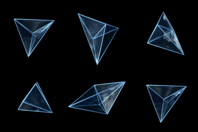
Although it may be embedded in two dimensions, the Desargues configuration has a very simple construction in three dimensions: for any configuration of five planes in general position in Euclidean space, the ten points where three planes meet and the ten lines formed by the intersection of two of the planes together form an instance of the configuration. [2] This construction is closely related to the property that every projective plane that can be embedded into a 3-dimensional projective space obeys Desargues' theorem. This three-dimensional realization of the Desargues configuration is also called the complete pentahedron. [2]

Four dimensions

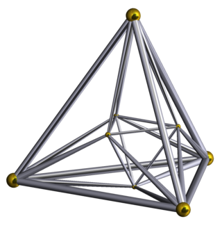
3D projection of the 5-cell, showing its vertices, edges, and ridges 5-cell.gif
3D projection of the 5-cell, showing its vertices, edges, and ridges

The 5-cell or pentatope (a regular simplex in four dimensions) has five vertices, ten edges, ten triangular ridges (2-dimensional faces), and five tetrahedral facets; the edges and ridges touch each other in the same pattern as the Desargues configuration. Extend each of the edges of the 5-cell to the line that contains it (its affine hull), similarly extend each triangle of the 5-cell to the 2-dimensional plane that contains it, and intersect these lines and planes by a three-dimensional hyperplane that neither contains nor is parallel to any of them. Each line intersects the hyperplane in a point, and each plane intersects the hyperplane in a line; these ten points and lines form an instance of the Desargues configuration. [2]

Symmetries

Although Desargues' theorem chooses different roles for its ten lines and points, the Desargues configuration itself is more symmetric: any of the ten points may be chosen to be the center of perspectivity, and that choice determines which six points will be the vertices of triangles and which line will be the axis of perspectivity. The Desargues configuration has a symmetry group of order 120; that is, there are 120 different ways of permuting the points and lines of the configuration in a way that preserves its point-line incidences. [3] The three-dimensional construction of the Desargues configuration makes these symmetries more readily apparent: if the configuration is generated from five planes in general position in three dimensions, then each of the 120 different permutations of these five planes corresponds to a symmetry of the configuration. [2]

The Desargues configuration is self-dual, meaning that it is possible to find a correspondence from points of one Desargues configuration to lines of a second configuration, and from lines of the first configuration to points of a second configuration, in such a way that all of the configuration's incidences are preserved. [4]

Graphs

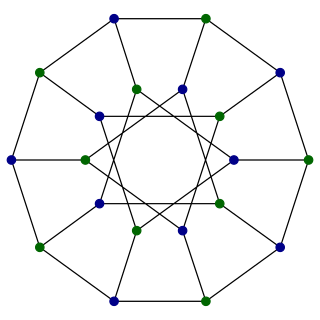
The Levi graph of the Desargues configuration, a graph having one vertex for each point or line in the configuration, is known as the Desargues graph. Because of the symmetries and self-duality of the Desargues configuration, the Desargues graph is a symmetric graph. [1]

The Petersen graph, in the layout shown by Kempe (1886) Petersen2 tiny.svg
The Petersen graph, in the layout shown by Kempe (1886)

Kempe (1886) draws a different graph for this configuration, with ten vertices representing its ten lines, and with two vertices connected by an edge whenever the corresponding two lines do not meet at one of the points of the configuration. Alternatively, the vertices of this graph may be interpreted as representing the points of the Desargues configuration, in which case the edges connect pairs of points for which the line connecting them is not part of the configuration. This publication marks the first known appearance of the Petersen graph in the mathematical literature, 12 years before Julius Petersen's use of the same graph as a counterexample to an edge coloring problem. [5]

A non-Desargues (103103) configuration. Non-Desargues configuration.svg
A non-Desargues (103103) configuration.

As a projective configuration, the Desargues configuration has the notation (103103), meaning that each of its ten points is incident to three lines and each of its ten lines is incident to three points. Its ten points can be viewed in a unique way as a pair of mutually inscribed pentagons, or as a self-inscribed decagon. [6] The Desargues graph, a 20-vertex bipartite symmetric cubic graph, is so called because it can be interpreted as the Levi graph of the Desargues configuration, with a vertex for each point and line of the configuration and an edge for every incident point-line pair. [1]

There also exist eight other (103103) configurations (that is, sets of points and lines in the Euclidean plane with three lines per point and three points per line) that are not incidence-isomorphic to the Desargues configuration, one of which is shown at right. A tenth configuration exists as an abstract finite geometry but cannot be realized using Euclidean points and lines. [7] In all of these configurations, each point has three other points that are not collinear with it. But in the Desargues configuration, these three points are always collinear with each other (if the chosen point is the center of perspectivity, then the three points form the axis of perspectivity) while in the other configuration shown in the illustration these three points form a triangle of three lines. As with the Desargues configuration, the other depicted configuration can be viewed as a pair of mutually inscribed pentagons. [8]

The Desargues configuration viewed as a pair of mutually inscribed pentagons: each pentagon vertex lies on the line through one of the sides of the other pentagon. Mutually-inscribed-pentagons.svg
The Desargues configuration viewed as a pair of mutually inscribed pentagons: each pentagon vertex lies on the line through one of the sides of the other pentagon.

Notes

Related Research Articles

<span class="mw-page-title-main">Dual polyhedron</span> Polyhedron associated with another by swapping vertices for faces

In geometry, every polyhedron is associated with a second dual structure, where the vertices of one correspond to the faces of the other, and the edges between pairs of vertices of one correspond to the edges between pairs of faces of the other. Such dual figures remain combinatorial or abstract polyhedra, but not all can also be constructed as geometric polyhedra. Starting with any given polyhedron, the dual of its dual is the original polyhedron.

<span class="mw-page-title-main">Projective geometry</span> Type of geometry

In mathematics, projective geometry is the study of geometric properties that are invariant with respect to projective transformations. This means that, compared to elementary Euclidean geometry, projective geometry has a different setting, projective space, and a selective set of basic geometric concepts. The basic intuitions are that projective space has more points than Euclidean space, for a given dimension, and that geometric transformations are permitted that transform the extra points to Euclidean points, and vice versa.
<span class="mw-page-title-main">Affine geometry</span> Euclidean geometry without distance and angles

In mathematics, affine geometry is what remains of Euclidean geometry when ignoring the metric notions of distance and angle.

<span class="mw-page-title-main">Desargues's theorem</span> Two triangles are in perspective axially if and only if they are in perspective centrally

In projective geometry, Desargues's theorem, named after Girard Desargues, states:

<span class="mw-page-title-main">Fano plane</span> Geometry with 7 points and 7 lines

In finite geometry, the Fano plane is a finite projective plane with the smallest possible number of points and lines: 7 points and 7 lines, with 3 points on every line and 3 lines through every point. These points and lines cannot exist with this pattern of incidences in Euclidean geometry, but they can be given coordinates using the finite field with two elements. The standard notation for this plane, as a member of a family of projective spaces, is PG(2, 2). Here, PG stands for "projective geometry", the first parameter is the geometric dimension and the second parameter is the order.

<span class="mw-page-title-main">Regular polytope</span> Polytope with highest degree of symmetry

In mathematics, a regular polytope is a polytope whose symmetry group acts transitively on its flags, thus giving it the highest degree of symmetry. In particular, all its elements or j-faces — cells, faces and so on — are also transitive on the symmetries of the polytope, and are themselves regular polytopes of dimension jn.

<span class="mw-page-title-main">16-cell</span> Four-dimensional analog of the octahedron

In geometry, the 16-cell is the regular convex 4-polytope (four-dimensional analogue of a Platonic solid) with Schläfli symbol {3,3,4}. It is one of the six regular convex 4-polytopes first described by the Swiss mathematician Ludwig Schläfli in the mid-19th century. It is also called C16, hexadecachoron, or hexdecahedroid [sic?].

<span class="mw-page-title-main">Incidence structure</span> Abstract mathematical system of two types of objects and a relation between them

In mathematics, an incidence structure is an abstract system consisting of two types of objects and a single relationship between these types of objects. Consider the points and lines of the Euclidean plane as the two types of objects and ignore all the properties of this geometry except for the relation of which points are incident on which lines for all points and lines. What is left is the incidence structure of the Euclidean plane.

<span class="mw-page-title-main">Arrangement of lines</span> Subdivision of the plane by lines

In geometry, an arrangement of lines is the subdivision of the plane formed by a collection of lines. Problems of counting the features of arrangements have been studied in discrete geometry, and computational geometers have found algorithms for the efficient construction of arrangements.

<span class="mw-page-title-main">Levi graph</span>

In combinatorial mathematics, a Levi graph or incidence graph is a bipartite graph associated with an incidence structure. From a collection of points and lines in an incidence geometry or a projective configuration, we form a graph with one vertex per point, one vertex per line, and an edge for every incidence between a point and a line. They are named for Friedrich Wilhelm Levi, who wrote about them in 1942.
<span class="mw-page-title-main">Desargues graph</span> Distance-transitive cubic graph with 20 nodes and 30 edges

In the mathematical field of graph theory, the Desargues graph is a distance-transitive, cubic graph with 20 vertices and 30 edges. It is named after Girard Desargues, arises from several different combinatorial constructions, has a high level of symmetry, is the only known non-planar cubic partial cube, and has been applied in chemical databases.
<span class="mw-page-title-main">Pappus configuration</span> Geometric configuration of 9 points and 9 lines

In geometry, the Pappus configuration is a configuration of nine points and nine lines in the Euclidean plane, with three points per line and three lines through each point.

<span class="mw-page-title-main">Configuration (geometry)</span> Points and lines with equal incidences

In mathematics, specifically projective geometry, a configuration in the plane consists of a finite set of points, and a finite arrangement of lines, such that each point is incident to the same number of lines and each line is incident to the same number of points.

<span class="mw-page-title-main">Möbius–Kantor graph</span> Symmetric bipartite cubic graph with 16 vertices and 24 edges

In the mathematical field of graph theory, the Möbius–Kantor graph is a symmetric bipartite cubic graph with 16 vertices and 24 edges named after August Ferdinand Möbius and Seligmann Kantor. It can be defined as the generalized Petersen graph G(8,3): that is, it is formed by the vertices of an octagon, connected to the vertices of an eight-point star in which each point of the star is connected to the points three steps away from it.

<span class="mw-page-title-main">Möbius–Kantor configuration</span> Geometric structure of 8 points and 8 lines

In geometry, the Möbius–Kantor configuration is a configuration consisting of eight points and eight lines, with three points on each line and three lines through each point. It is not possible to draw points and lines having this pattern of incidences in the Euclidean plane, but it is possible in the complex projective plane.

<span class="mw-page-title-main">Perspective (geometry)</span> Term in geometry

Two figures in a plane are perspective from a pointO, called the center of perspectivity, if the lines joining corresponding points of the figures all meet at O. Dually, the figures are said to be perspective from a line if the points of intersection of corresponding lines all lie on one line. The proper setting for this concept is in projective geometry where there will be no special cases due to parallel lines since all lines meet. Although stated here for figures in a plane, the concept is easily extended to higher dimensions.

<span class="mw-page-title-main">Reye configuration</span> Geometric configuration of 12 points and 6 lines

In geometry, the Reye configuration, introduced by Theodor Reye (1882), is a configuration of 12 points and 16 lines. Each point of the configuration belongs to four lines, and each line contains three points. Therefore, in the notation of configurations, the Reye configuration is written as 124163.

<span class="mw-page-title-main">Cremona–Richmond configuration</span>

In mathematics, the Cremona–Richmond configuration is a configuration of 15 lines and 15 points, having 3 points on each line and 3 lines through each point, and containing no triangles. It was studied by Cremona and Richmond. It is a generalized quadrangle with parameters (2,2). Its Levi graph is the Tutte–Coxeter graph.

<span class="mw-page-title-main">Grünbaum–Rigby configuration</span>

In geometry, the Grünbaum–Rigby configuration is a symmetric configuration consisting of 21 points and 21 lines, with four points on each line and four lines through each point. Originally studied by Felix Klein in the complex projective plane in connection with the Klein quartic, it was first realized in the Euclidean plane by Branko Grünbaum and John F. Rigby.
<span class="mw-page-title-main">Danzer's configuration</span>

In mathematics, Danzer's configuration is a self-dual configuration of 35 lines and 35 points, having 4 points on each line and 4 lines through each point. It is named after the German geometer Ludwig Danzer and was popularised by Branko Grünbaum. The Levi graph of the configuration is the Kronecker cover of the odd graph O4, and is isomorphic to the middle layer graph of the seven-dimensional hypercube graph Q7. The middle layer graph of an odd-dimensional hypercube graph Q2n+1(n,n+1) is a subgraph whose vertex set consists of all binary strings of length 2n + 1 that have exactly n or n + 1 entries equal to 1, with an edge between any two vertices for which the corresponding binary strings differ in exactly one bit. Every middle layer graph is Hamiltonian.
References