In an electric power system, a fault or fault current is any abnormal electric current. For example, a short circuit is a fault in which current bypasses the normal load. An open-circuit fault occurs if a circuit is interrupted by some failure. In three-phase systems, a fault may involve one or more phases and ground, or may occur only between phases. In a "ground fault" or "earth fault", current flows into the earth. The prospective short-circuit current of a predictable fault can be calculated for most situations. In power systems, protective devices can detect fault conditions and operate circuit breakers and other devices to limit the loss of service due to a failure.
An electric power system is a network of electrical components deployed to supply, transfer, and use electric power. An example of an electric power system is the grid that provides power to an extended area. An electrical grid power system can be broadly divided into the generators that supply the power, the transmission system that carries the power from the generating centres to the load centres, and the distribution system that feeds the power to nearby homes and industries. Smaller power systems are also found in industry, hospitals, commercial buildings and homes. The majority of these systems rely upon three-phase AC power—the standard for large-scale power transmission and distribution across the modern world. Specialised power systems that do not always rely upon three-phase AC power are found in aircraft, electric rail systems, ocean liners and automobiles.
An electric current is the rate of flow of electric charge past a point or region. An electric current is said to exist when there is a net flow of electric charge through a region. In electric circuits this charge is often carried by electrons moving through a wire. It can also be carried by ions in an electrolyte, or by both ions and electrons such as in an ionized gas (plasma).
A short circuit is an electrical circuit that allows a current to travel along an unintended path with no or a very low electrical impedance. This results in an excessive amount of current flowing into the circuit. The electrical opposite of a short circuit is an "open circuit", which is an infinite resistance between two nodes. It is common to misuse "short circuit" to describe any electrical malfunction, regardless of the actual problem.
In a polyphase system, a fault may affect all phases equally which is a "symmetrical fault". If only some phases are affected, the resulting "asymmetrical fault" becomes more complicated to analyse. The analysis of these types of faults is often simplified by using methods such as symmetrical components.
A polyphase system is a means of distributing alternating-current electrical power where the power transfer is constant during each electrical cycle. Polyphase systems have three or more energized electrical conductors carrying alternating currents with a defined phase angle between the voltage waves in each conductor; for three-phase voltage, the phase angle is 120° or ~2.09 radians. Polyphase systems are particularly useful for transmitting power to electric motors which rely on alternating current to rotate. The most common example is the three-phase power system used for industrial applications and for power transmission. Compared to a single-phase, two-wire system, a three-phase three-wire system transmits three times as much power for the same conductor size and voltage.
In electrical engineering, the method of symmetrical components simplifies analysis of unbalanced three-phase power systems under both normal and abnormal conditions. The basic idea is that an asymmetrical set of N phasors can be expressed as a linear combination of N symmetrical sets of phasors by means of a complex linear transformation.
The design of systems to detect and interrupt power system faults is the main objective of power-system protection.
Power-system protection is a branch of electrical power engineering that deals with the protection of electrical power systems from faults through the disconnection of faulted parts from the rest of the electrical network. The objective of a protection scheme is to keep the power system stable by isolating only the components that are under fault, whilst leaving as much of the network as possible still in operation. Thus, protection schemes must apply a very pragmatic and pessimistic approach to clearing system faults. The devices that are used to protect the power systems from faults are called protection devices.
Transient fault
A transient fault is a fault that is no longer present if power is disconnected for a short time and then restored; or an insulation fault which only temporarily affects a device's dielectric properties which are restored after a short time. Many faults in overhead power lines are transient in nature. When a fault occurs, equipment used for power system protection operate to isolate the area of the fault. A transient fault will then clear and the power-line can be returned to service. Typical examples of transient faults include:
An overhead power line is a structure used in electric power transmission and distribution to transmit electrical energy along large distances. It consists of one or more conductors suspended by towers or poles. Since most of the insulation is provided by air, overhead power lines are generally the lowest-cost method of power transmission for large quantities of electric energy.
A lightning strike or lightning bolt is an electric discharge between the atmosphere and an object. They mostly originate in a cumulonimbus cloud and terminate on the ground, called cloud to ground (CG) lightning. A less common type of strike, called ground to cloud (GC), is upward propagating lightning initiated from a tall grounded object and reaches into the clouds. About 25% of all lightning events worldwide are strikes between the atmosphere and earth-bound objects. The bulk of lightning events are intra-cloud (IC) or cloud to cloud (CC), where discharges only occur high in the atmosphere. Lightning strikes the average commercial aircraft at least once a year, but modern engineering and design means this is rarely a problem. The movement of aircraft through clouds can even cause lightning strikes.
Conductor clashing is the phenomenon where conductors come in contact with one another during high wind speeds or gusts.
Transmission and distribution systems use an automatic re-close function which is commonly used on overhead lines to attempt to restore power in the event of a transient fault. This functionality is not as common on underground systems as faults there are typically of a persistent nature. Transient faults may still cause damage both at the site of the original fault or elsewhere in the network as fault current is generated.
Electric power transmission is the bulk movement of electrical energy from a generating site, such as a power plant, to an electrical substation. The interconnected lines which facilitate this movement are known as a transmission network. This is distinct from the local wiring between high-voltage substations and customers, which is typically referred to as electric power distribution. The combined transmission and distribution network is known as the "power grid" in North America, or just "the grid". In the United Kingdom, India, Myanmar, Malaysia and New Zealand, the network is known as the "National Grid".
Electric power distribution is the final stage in the delivery of electric power; it carries electricity from the transmission system to individual consumers. Distribution substations connect to the transmission system and lower the transmission voltage to medium voltage ranging between 2 kV and 35 kV with the use of transformers. Primary distribution lines carry this medium voltage power to distribution transformers located near the customer's premises. Distribution transformers again lower the voltage to the utilization voltage used by lighting, industrial equipment or household appliances. Often several customers are supplied from one transformer through secondary distribution lines. Commercial and residential customers are connected to the secondary distribution lines through service drops. Customers demanding a much larger amount of power may be connected directly to the primary distribution level or the subtransmission level.
Persistent fault
A persistent fault is present regardless of power being applied. Faults in underground power cables are most often persistent due to mechanical damage to the cable, but are sometimes transient in nature due to lightning.[1]
Symmetric fault
A symmetric or balanced fault affects each of the three phases equally. In transmission line faults, roughly 5% are symmetric.[2] This is in contrast to an asymmetrical fault, where the three phases are not affected equally.
Asymmetric fault
An asymmetric or unbalanced fault does not affect each of the three phases equally. Common types of asymmetric faults, and their causes:
line-to-line - a short circuit between lines, caused by ionization of air, or when lines come into physical contact, for example due to a broken insulator. In transmission line faults, roughly 5% - 10% are asymmetric line-to-line faults.[3]
line-to-ground - a short circuit between one line and ground, very often caused by physical contact, for example due to lightning or other storm damage. In transmission line faults, roughly 65% - 70% are asymmetric line-to-ground faults.[4]
double line-to-ground - two lines come into contact with the ground (and each other), also commonly due to storm damage. In transmission line faults, roughly 15% - 20% are asymmetric double line-to-ground.[5]
Bolted fault
One extreme is where the fault has zero impedance, giving the maximum prospective short-circuit current. Notionally, all the conductors are considered connected to ground as if by a metallic conductor; this is called a "bolted fault". It would be unusual in a well-designed power system to have a metallic short circuit to ground but such faults can occur by mischance. In one type of transmission line protection, a "bolted fault" is deliberately introduced to speed up operation of protective devices.
Ground fault (earth fault)
A ground fault (earth fault) is any failure that allows unintended connection of power circuit conductors with the earth. Such faults can cause objectionable circulating currents, or may energize the housings of equipment at a dangerous voltage. Some special power distribution systems may be designed to tolerate a single ground fault and continue in operation. Wiring codes may require an insulation monitoring device to give an alarm in such a case, so the cause of the ground fault can be identified and remedied. If a second ground fault develops in such a system, it can result in overcurrent or failure of components. Even in systems that are normally connected to ground to limit overvoltages, some applications require a Ground Fault Interrupter or similar device to detect faults to ground.
Realistic faults
Realistically, the resistance in a fault can be from close to zero to fairly high relative to the load resistance. A large amount of power may be consumed in the fault, compared with the zero-impedance case where the power is zero. Also, arcs are highly non-linear, so a simple resistance is not a good model. All possible cases need to be considered for a good analysis.[6]
Arcing fault
Where the system voltage is high enough, an electric arc may form between power system conductors and ground. Such an arc can have a relatively high impedance (compared to the normal operating levels of the system) and can be difficult to detect by simple overcurrent protection. For example, an arc of several hundred amperes on a circuit normally carrying a thousand amperes may not trip overcurrent circuit breakers but can do enormous damage to bus bars or cables before it becomes a complete short circuit. Utility, industrial, and commercial power systems have additional protection devices to detect relatively small but undesired currents escaping to ground. In residential wiring, electrical regulations may now require Arc-fault circuit interrupters on building wiring circuits, to detect small arcs before they cause damage or a fire.
Analysis
Symmetric faults can be analyzed via the same methods as any other phenomena in power systems, and in fact many software tools exist to accomplish this type of analysis automatically (see power flow study). However, there is another method which is as accurate and is usually more instructive.
First, some simplifying assumptions are made. It is assumed that all electrical generators in the system are in phase, and operating at the nominal voltage of the system. Electric motors can also be considered to be generators, because when a fault occurs, they usually supply rather than draw power. The voltages and currents are then calculated for this base case.
Next, the location of the fault is considered to be supplied with a negative voltage source, equal to the voltage at that location in the base case, while all other sources are set to zero. This method makes use of the principle of superposition.
To obtain a more accurate result, these calculations should be performed separately for three separate time ranges:
subtransient is first, and is associated with the largest currents
transient comes between subtransient and steady-state
steady-state occurs after all the transients have had time to settle
An asymmetric fault breaks the underlying assumptions used in three-phase power, namely that the load is balanced on all three phases. Consequently, it is impossible to directly use tools such as the one-line diagram, where only one phase is considered. However, due to the linearity of power systems, it is usual to consider the resulting voltages and currents as a superposition of symmetrical components, to which three-phase analysis can be applied.
In the method of symmetric components, the power system is seen as a superposition of three components:
a positive-sequence component, in which the phases are in the same order as the original system, i.e., a-b-c
a negative-sequence component, in which the phases are in the opposite order as the original system, i.e., a-c-b
a zero-sequence component, which is not truly a three-phase system, but instead all three phases are in phase with each other.
To determine the currents resulting from an asymmetrical fault, one must first know the per-unit zero-, positive-, and negative-sequence impedances of the transmission lines, generators, and transformers involved. Three separate circuits are then constructed using these impedances. The individual circuits are then connected together in a particular arrangement that depends upon the type of fault being studied (this can be found in most power systems textbooks). Once the sequence circuits are properly connected, the network can then be analyzed using classical circuit analysis techniques. The solution results in voltages and currents that exist as symmetrical components; these must be transformed back into phase values by using the A matrix.
Analysis of the prospective short-circuit current is required for selection of protective devices such as fuses and circuit breakers. If a circuit is to be properly protected, the fault current must be high enough to operate the protective device within as short a time as possible; also the protective device must be able to withstand the fault current and extinguish any resulting arcs without itself being destroyed or sustaining the arc for any significant length of time.
The magnitude of fault currents differ widely depending on the type of earthing system used, the installation's supply type and earthing system, and its proximity to the supply. For example, for a domestic UK 230 V, 60 A TN-S or USA 120 V/240 V supply, fault currents may be a few thousand amperes. Large low-voltage networks with multiple sources may have fault levels of 300,000 amperes. A high-resistance-grounded system may restrict line to ground fault current to only 5 amperes. Prior to selecting protective devices, prospective fault current must be measured reliably at the origin of the installation and at the furthest point of each circuit, and this information applied properly to the application of the circuits.
Detecting and locating faults
Overhead power lines are easiest to diagnose since the problem is usually obvious, e.g., a tree has fallen across the line, or a utility pole is broken and the conductors are lying on the ground.
Locating faults in a cable system can be done either with the circuit de-energized, or in some cases, with the circuit under power. Fault location techniques can be broadly divided into terminal methods, which use voltages and currents measured at the ends of the cable, and tracer methods, which require inspection along the length of the cable. Terminal methods can be used to locate the general area of the fault, to expedite tracing on a long or buried cable.[7]
In very simple wiring systems, the fault location is often found through inspection of the wires. In complex wiring systems (for example, aircraft wiring) where the wires may be hidden, wiring faults are located with a Time-domain reflectometer.[8] The time domain reflectometer sends a pulse down the wire and then analyzes the returning reflected pulse to identify faults within the electrical wire.
In historic submarine telegraph cables, sensitive galvanometers were used to measure fault currents; by testing at both ends of a faulted cable, the fault location could be isolated to within a few miles, which allowed the cable to be grappled up and repaired. The Murray loop and the Varley loop were two types of connections for locating faults in cables
Sometimes an insulation fault in a power cable will not show up at lower voltages. A "thumper" test set applies a high-energy, high-voltage pulse to the cable. Fault location is done by listening for the sound of the discharge at the fault. While this test contributes to damage at the cable site, it is practical because the faulted location would have to be re-insulated when found in any case.[9]
In a high resistance grounded distribution system, a feeder may develop a fault to ground but the system continues in operation. The faulted, but energized, feeder can be found with a ring-type current transformer collecting all the phase wires of the circuit; only the circuit containing a fault to ground will show a net unbalanced current. To make the ground fault current easier to detect, the grounding resistor of the system may be switched between two values so that the fault current pulses.
In Australia, when this information is not given, the prospective fault current in amperes "should be considered to be 6 times the nominal battery capacity at the C120 A·h rate," according to AS 4086 part 2 (Appendix H).
Three-phase electric power is a common method of alternating current electric power generation, transmission, and distribution. It is a type of polyphase system and is the most common method used by electrical grids worldwide to transfer power. It is also used to power large motors and other heavy loads.
In electrical engineering, ground or earth is the reference point in an electrical circuit from which voltages are measured, a common return path for electric current, or a direct physical connection to the earth.
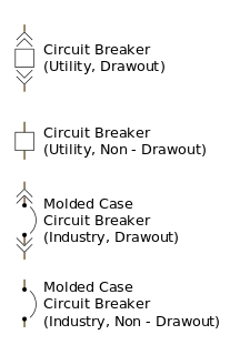
A circuit breaker is an automatically operated electrical switch designed to protect an electrical circuit from damage caused by excess current from an overload or short circuit. Its basic function is to interrupt current flow after a fault is detected. Unlike a fuse, which operates once and then must be replaced, a circuit breaker can be reset to resume normal operation.
A residual-current device (RCD), or residual-current circuit breaker (RCCB), is a device that instantly breaks an electric circuit to prevent serious harm from an ongoing electric shock. Injury may still occur in some cases, for example if a human falls after receiving a shock, or if the person touches both conductors at the same time.
In electronics and electrical engineering, a fuse is an electrical safety device that operates to provide overcurrent protection of an electrical circuit. Its essential component is a metal wire or strip that melts when too much current flows through it, thereby interrupting the current. It is a sacrificial device; once a fuse has operated it is an open circuit, and it must be replaced or rewired, depending on type.
An arc-fault circuit interrupter (AFCI) also known as an arc-fault detection device (AFDD) is a circuit breaker that breaks the circuit when it detects an electric arc in the circuit it protects to prevent electrical fires. An AFCI selectively distinguishes between a harmless arc, and a potentially dangerous arc.
Electrical wiring in the United Kingdom is commonly understood to be an electrical installation for operation by end users within domestic, commercial, industrial, and other buildings, and also in special installations and locations, such as marinas or caravan parks. It does not normally cover the transmission of electrical power to them.
The prospective short-circuit current (PSCC), available fault current, or short-circuit making current is the highest electric current which can exist in a particular electrical system under short-circuit conditions. It is determined by the voltage and impedance of the supply system. It is of the order of a few thousand amperes for a standard domestic mains electrical installation, but may be as low as a few milliamperes in a separated extra-low voltage (SELV) system or as high as hundreds of thousands of amps in large industrial power systems.
A current transformer (CT) is a type of transformer that is used to measure alternating current (AC). It produces a current in its secondary which is proportional to the current in its primary.
In electric power distribution, automatic circuit reclosers (ACRs) are a class of switchgear which is designed for use on overhead electricity distribution networks to detect and interrupt momentary faults. Also known as Reclosers or Autoreclosers, ACRs are essentially high voltage rated circuit breakers with integrated current and voltage sensors and a protection relay, optimized for use as an overhead network distribution protection asset. Commercial ACRs are governed by the ANSI/IEEE C37.60, IEC 62271-111 and IEC 62271-200 standards. The three major classes of operating voltage are 15.5 kV, 27 kV and 38 kV.
In an electrical installation, an earthing system or grounding system connects specific parts of that installation with the Earth's conductive surface for safety and functional purposes. The point of reference is the Earth's conductive surface. The choice of earthing system can affect the safety and electromagnetic compatibility of the installation. Regulations for earthing systems vary considerably among countries, though most follow the recommendations of the International Electrotechnical Commission. Regulations may identify special cases for earthing in mines, in patient care areas, or in hazardous areas of industrial plants.
Extra-low voltage (ELV) is an electricity supply voltage in a range which carries a low risk of dangerous electrical shock. There are various standards that define extra-low voltage. The International Electrotechnical Commission member organizations and the UK IET define an ELV device or circuit as one in which the electrical potential between conductor or electrical conductor and earth (ground) does not exceed 50 V a.c. or 120 V d.c.. EU's Low Voltage Directive applies from 50 V a.c. or 75 V d.c.
This is an alphabetical list of articles pertaining specifically to electrical and electronics engineering. For a thematic list, please see List of electrical engineering topics. For a broad overview of engineering, see List of engineering topics. For biographies, see List of engineers.
A decoupling capacitor is a capacitor used to decouple one part of an electrical network (circuit) from another. Noise caused by other circuit elements is shunted through the capacitor, reducing the effect it has on the rest of the circuit. An alternative name is bypass capacitor as it is used to bypass the power supply or other high impedance component of a circuit.
Breaking capacity or interrupting rating is the current that a fuse, circuit breaker, or other electrical apparatus is able to interrupt without being destroyed or causing an electric arc with unacceptable duration. The prospective short-circuit current which can occur under short circuit conditions should not exceed the rated breaking capacity of the apparatus, otherwise breaking of the current cannot be guaranteed. The current breaking capacity corresponds to a certain voltage, so an electrical apparatus may have more than one breaking capacity current, according to the actual operating voltage. Breaking current may be stated in terms of the total current or just in terms of the alternating-current (symmetrical) component. Since the time of opening of a fuse or switch is not coordinated with the reversal of the alternating current, in some circuits the total current may be offset and can be larger than the alternating-current component by itself.
A variety of types of electrical transformer are made for different purposes. Despite their design differences, the various types employ the same basic principle as discovered in 1831 by Michael Faraday, and share several key functional parts.
Most of the terms listed in Wikipedia glossaries are already defined and explained within Wikipedia itself. However, glossaries like this one are useful for looking up, comparing and reviewing large numbers of terms together. You can help enhance this page by adding new terms or writing definitions for existing ones.
This page is based on this Wikipedia article Text is available under the CC BY-SA 4.0 license; additional terms may apply. Images, videos and audio are available under their respective licenses.