A preserved hit-and-miss engine: 1917 Amanco 2+1⁄4hp (1.7kW) 'Hired Man'
A hit-and-miss engine or Hit 'N' Miss is a type of stationaryinternal combustion engine that is controlled by a governor to only fire at a set speed. They are usually 4-stroke but 2-stroke versions were made. It was conceived in the late 19th century and produced by various companies from the 1890s through approximately the 1940s. The name comes from the speed control on these engines: they fire ("hit") only when operating at or below a set speed, and cycle without firing ("miss") when they exceed their set speed. This is as compared to the "throttle governed" method of speed control. The sound made when the engine is running without a load is a distinctive "Snort POP whoosh whoosh whoosh whoosh snort POP" as the engine fires and then coasts until the speed decreases and it fires again to maintain its average speed. The snorting is caused by the atmospheric intake valve used on many of these engines.
In the Canadian Atlantic Provinces, primarily in Newfoundland, these engines were known, in colloquial conversation, as "Make-and-Break" engines. The main usage here was to drive traditional skiff style utility and fishing boats.
Construction
This is a video montage of the Otto engines running at the Western Minnesota Steam Threshers Reunion (WMSTR), in Rollag, Minnesota. It is a type of hit-and-miss engine.(2min 16sec, 320x240, 340kbit/s video)
A hit-and-miss engine is a type of flywheel engine.[1] A flywheel engine is an engine that has a large flywheel or set of flywheels connected to the crankshaft. The flywheels maintain engine speed during engine cycles that do not produce driving mechanical forces. The flywheels store energy on the combustion stroke and supply the stored energy to the mechanical load on the other three strokes of the piston. When these engines were designed, technology was less advanced and manufacturers made all parts very large. A typical 6 horsepower (4.5kW) engine weighs approximately 1000 pounds (454kg). Typically, the material for all significant engine parts was cast iron. Small functional pieces were made of steel and machined to tolerance.[1]
The fuel system of a hit-and-miss engine consists of a fuel tank, fuel line, check valve and fuel mixer. The fuel tank most typically holds gasoline but many users started the engines with gasoline and then switched to a cheaper fuel, such as kerosene or diesel. The fuel line connects the fuel tank to the mixer. Along the fuel line, a check valve keeps the fuel from running back to the tank between combustion strokes. The mixer creates the correct fuel-air mixture by means of a needle valve attached to a weighted or spring-loaded piston usually in conjunction with an oil-damped dashpot.
Mixer operation is simple, it contains only one moving part, that being the needle valve. While there are exceptions, a mixer doesn't store fuel in a bowl of any kind. Fuel is simply fed to the mixer, where due to the effect of Bernoulli's principle, it is self-metered in the venturi created below the weighted piston by the action of the attached needle valve, the method used to this day in the SU carburetor.
Sparks to ignite the fuel mixture are created by either a spark plug or a device called an ignitor. When a spark plug is used, the spark was generated by either a magneto or else a trembler (or 'buzz') coil. A buzz coil uses battery power to generate a continuous series of high voltage pulses that are fed to the spark plug. For igniter ignition, either a battery and coil is used or a "low tension" magneto is used. With battery and coil ignition, a battery is wired in series with a wire coil and the igniter contacts. When the contacts of the ignitor are closed (the contacts reside inside the combustion chamber), electricity flows through the circuit. When the contacts are opened by the timing mechanism, a spark is generated across the contacts, which ignite the mixture. When a low tension magneto (really a low-voltage high-current generator) is used, the output of the magneto is fed directly to the igniter points and the spark is generated as with a battery and coil.
Except for very large examples, lubrication was almost always manual. Main crankshaft bearings and the connecting rod bearing on the crankshaft generally has a grease cup—a small container (cup) filled with grease and a screwed-on cover.
A typical engine oiler. This is one made by Lunkenheimer
When the cover is screwed down tighter, grease is forced out of the bottom of the cup and into the bearing. Some early engines have just a hole in the bearing casting cap where an operator squirts lubricating oil while the engine is running. The piston is lubricated by a drip oiler that continuously feeds drips of oil onto the piston. The excess oil from the piston runs out of the cylinder onto the engine and eventually onto the ground. The drip oiler can be adjusted to drip faster or slower depending on the need for lubrication, dictated by how hard the engine is working. The rest of the moving engine components were all lubricated by oil that the engine operator had to apply periodically while the engine was running.
Virtually all hit-and-miss engines are of the "open crank" style, that is, there is no enclosed crankcase. The crankshaft, connecting rod, camshaft, gears, governor, etc. are all completely exposed and can be viewed in operation when the engine is running. This makes for a messy environment as oil and sometimes grease are thrown from the engine as well as oil running onto the ground. Another disadvantage is that dirt and dust can get on all moving engine parts, causing excessive wear and engine malfunctions. Frequent cleaning of the engine is therefore required to keep it in proper operating condition.
Cooling of the majority of hit-and-miss engines is by hopper cooling, with water in an open reservoir. There was a small portion of small and fractional horsepower engines that were air-cooled with the aid of an incorporated fan. The water-cooled engine has a built in reservoir (larger engines usually don't have a reservoir and require connection to a large external tank for cooling water via pipe connections on the cylinder). The water reservoir includes the area around the cylinder as well as the cylinder head (most cases) and a tank mounted or cast above the cylinder. When the engine runs it heats the water. Cooling is accomplished by the water steaming off and removing heat from the engine. When an engine runs under load for a period of time, it is common for the water in the reservoir to boil. Replacement of lost water is needed from time to time. A danger of the water-cooled design is freezing in cold weather. Many engines were ruined when a forgetful operator neglected to drain the water when the engine was not in use, and the water froze and broke the cast iron engine pieces. However, New Holland patented a v-shaped reservoir, so that expanding ice pushed up and into a larger space rather than break the reservoir. Water jacket repairs are common on many of the engines that still exist.
Design
These were simple engines compared to modern engine design. However, they incorporate some innovative designs in several areas, often in an attempt to circumvent patent infringement for a particular component. This is particularly true of the governor. Governors are centrifugal, swinging arm, pivot arm, and many others. The actuator mechanism to govern speed is also varied depending on patents existing and the governor used. See, for example, U.S. Patents 543,157[2] from 1895 or 980,658[3] from 1911. However accomplished, the governor has one job - to control the speed of the engine. In modern engines, power output is controlled by throttling the flow of the air through the intake by means of a butterfly valve; the only exception to this being in diesels and Valvetronic petrol engines.
Operation
The intake valve on hit-and-miss engines has no actuator; instead, a light spring holds the intake valve closed unless a vacuum in the cylinder draws it open. This vacuum only occurs if the exhaust valve is closed during the piston's down-stroke. When the hit-and-miss engine is operating above its set speed, the governor holds the exhaust valve open, preventing a vacuum in the cylinder and causing the intake valve to remain closed, thus interrupting the Otto cycle firing mechanism. When the engine is operating at or below its set speed, the governor lets the exhaust valve close. On the next down-stroke, a vacuum in the cylinder opens the intake valve and lets the fuel-air mixture enter. This mechanism prevents fuel consumption during the intake stroke of "miss" cycles.
A video explanation on the workings of a hit and miss engine can be found here
Usage
A Jaeger trash pump used for pumping dirty (trashy) water. It has a Hercules 2½ HP (1.9 kW) engine. This is an example of an integrated function of hit-and-miss engines (i.e., not belted)
Hit-and-miss engines produced power outputs from 1 through approximately 100 horsepower (0.75 - 75kW). These engines run slowly—typically from 250 revolutions per minute (rpm) for large horsepower engines to 600 rpm for small horsepower engines. They powered pumps for cultivation, saws for cutting wood, generators for electricity in rural areas, farm equipment, and many other stationary applications. Some were mounted on cement mixers. These engines also ran some early washing machines. They were a labour-saving device on farms, and helped farmers accomplish much more than they could previously.
The engine was typically belted to the device being powered by a wide flat belt, typically from 2 - 6 inches (5 – 15cm) wide. The flat belt was driven by a pulley on the engine that attached either to a flywheel or to the crankshaft. The pulley was specially made to have a circumference slightly tapered from the middle to each edge (like an over-inflated car tyre) so that the middle of the pulley was a slightly larger diameter. This kept the flat belt in the centre of the pulley.
Replacement with throttle-governed engines
By the 1930s, more-advanced engines became common. Flywheel engines are extremely heavy for the power produced, and run at very slow speeds. Older engines required a lot of maintenance and were not easily incorporated into mobile applications.
In the late 1920s, International Harvester already had the model M engine, which was an enclosed version of a flywheel engine. Their next step was the model LA, which was a totally enclosed engine (except for the valve system) featuring self-lubrication (oil in the crankcase), reliable spark plug ignition, faster-speed operation (up to about 750-800 RPM) and most of all, light in weight compared to earlier generations. While the 1½ HP (1.1kW) model LA still weighed about 150 pounds (68kg), it was far lighter than the model M 1½ HP engine, which is in the 300-350 pound (136 – 159kg) range. Later a slightly improved LA, the LB was produced. The models M, LA and LB are throttle governed. As time passed, more engine manufacturers moved to the enclosed crankcase engine. Companies like Briggs and Stratton were also producing lightweight air-cooled engines in the 1/2 to 2 HP (.37 - 1.5kW) range and used much lighter-weight materials. These engines also run at much higher speeds (up to approximately 2,000-4,000 RPM) and therefore produce more power for a given size than slow flywheel engines.
Most flywheel engine production ceased in the 1940s, but modern engines of this kind remain in use for applications where the low speed is desirable, mostly in oil field applications such as pumpjacks. Maintenance is less of a problem with modern flywheel engines than older ones due to their enclosed crankcases and more advanced materials.
Preservation
Thousands of out-of-use flywheel engines were scrapped in the iron and steel drives of World War II—but many survived and have been restored to working order by enthusiasts. Numerous preserved hit-and-miss engines may be seen in action at shows dedicated to antique engines (which often also have antique tractors), as well as in the stationary engine section of steam fairs, vintage vehicle rallies, and county fairs.
A reciprocating engine, also often known as a piston engine, is typically a heat engine that uses one or more reciprocating pistons to convert high temperature and high pressure into a rotating motion. This article describes the common features of all types. The main types are: the internal combustion engine, used extensively in motor vehicles; the steam engine, the mainstay of the Industrial Revolution; and the Stirling engine for niche applications. Internal combustion engines are further classified in two ways: either a spark-ignition (SI) engine, where the spark plug initiates the combustion; or a compression-ignition (CI) engine, where the air within the cylinder is compressed, thus heating it, so that the heated air ignites fuel that is injected then or earlier.
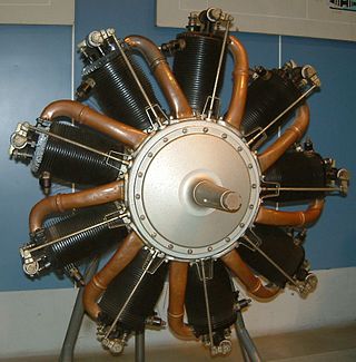
The rotary engine is an early type of internal combustion engine, usually designed with an odd number of cylinders per row in a radial configuration. The engine's crankshaft remained stationary in operation, while the entire crankcase and its attached cylinders rotated around it as a unit. Its main application was in aviation, although it also saw use in a few early motorcycles and automobiles.
A two-strokeengine is a type of internal combustion engine that completes a power cycle with two strokes of the piston in one revolution of the crankshaft. A four-stroke engine requires four strokes of the piston to complete a power cycle in two crankshaft revolutions. In a two-stroke engine, the end of the combustion stroke and the beginning of the compression stroke happen simultaneously, with the intake and exhaust functions occurring at the same time.
A four-strokeengine is an internal combustion (IC) engine in which the piston completes four separate strokes while turning the crankshaft. A stroke refers to the full travel of the piston along the cylinder, in either direction. The four separate strokes are termed:
Intake: Also known as induction or suction. This stroke of the piston begins at top dead center (T.D.C.) and ends at bottom dead center (B.D.C.). In this stroke the intake valve must be in the open position while the piston pulls an air-fuel mixture into the cylinder by producing a partial vacuum in the cylinder through its downward motion.
Compression: This stroke begins at B.D.C, or just at the end of the suction stroke, and ends at T.D.C. In this stroke the piston compresses the air-fuel mixture in preparation for ignition during the power stroke (below). Both the intake and exhaust valves are closed during this stage.
Combustion: Also known as power or ignition. This is the start of the second revolution of the four stroke cycle. At this point the crankshaft has completed a full 360 degree revolution. While the piston is at T.D.C. the compressed air-fuel mixture is ignited by a spark plug or by heat generated by high compression, forcefully returning the piston to B.D.C. This stroke produces mechanical work from the engine to turn the crankshaft.
Exhaust: Also known as outlet. During the exhaust stroke, the piston, once again, returns from B.D.C. to T.D.C. while the exhaust valve is open. This action expels the spent air-fuel mixture through the exhaust port.
The Monosoupape, was a rotary engine design first introduced in 1913 by Gnome Engine Company. It used a clever arrangement of internal transfer ports and a single pushrod-operated exhaust valve to replace the many moving parts found on more conventional rotary engines, and made the Monosoupape engines some of the most reliable of the era. British aircraft designer Thomas Sopwith described the Monosoupape as "one of the greatest single advances in aviation".
A crankcase is the housing in a piston engine that surrounds the crankshaft. In most modern engines, the crankcase is integrated into the engine block.
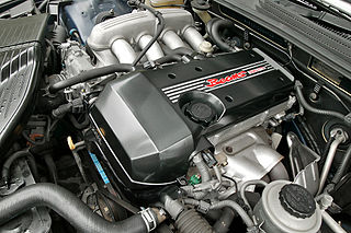
The Toyota S Series engines are a family of straight-four petrol engines with displacements between 1.8 and 2.2 litres, produced by Toyota Motor Corporation from January 1980 to August 2007. The S series has cast iron engine blocks and aluminium cylinder heads. This engine was designed around the new LASRE technology for lighter weight – such as sintered hollow camshafts.
The hot-bulb engine, also known as a semi-diesel, is a type of internal combustion engine in which fuel ignites by coming in contact with a red-hot metal surface inside a bulb, followed by the introduction of air (oxygen) compressed into the hot-bulb chamber by the rising piston. There is some ignition when the fuel is introduced, but it quickly uses up the available oxygen in the bulb. Vigorous ignition takes place only when sufficient oxygen is supplied to the hot-bulb chamber on the compression stroke of the engine.
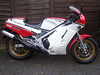
The Yamaha RD500LC is a high-performance, two-stroke sports motorcycle, also known as the RZ500 in Canada and Australia. A lightened but detuned version known as the RZV500R was developed for the Japanese home market. Strict United States Environmental Protection Agency regulations meant that the RZ500 was not available for sale in that country. Produced for a short period between 1984 and 1986 it has become a sought after collector's machine.
Internal combustion engines come in a wide variety of types, but have certain family resemblances, and thus share many common types of components.
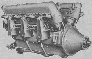
The Lorraine 12H Pétrel was a French V-12 supercharged, geared piston aeroengine initially rated at 370 kW (500 hp), but later developed to give 640 kW (860 hp). It powered a variety of mostly French aircraft in the mid-1930s, several on an experimental basis.
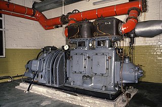
High-speed steam engines were one of the final developments of the stationary steam engine. They ran at a high speed, of several hundred rpm, which was needed by tasks such as electricity generation.
An internal combustion engine is a heat engine in which the combustion of a fuel occurs with an oxidizer in a combustion chamber that is an integral part of the working fluid flow circuit. In an internal combustion engine, the expansion of the high-temperature and high-pressure gases produced by combustion applies direct force to some component of the engine. The force is typically applied to pistons, turbine blades, a rotor, or a nozzle. This force moves the component over a distance, transforming chemical energy into kinetic energy which is used to propel, move or power whatever the engine is attached to.
The MWM AKD 112 Z is an air-cooled two-cylinder inline diesel engine produced by MWM from 1955 – 1960. One, three and four cylinder variants of the same engine family were also produced by MWM.
The 4 VD 14,5/12-1 SRW is an inline four-cylinder diesel engine produced by the VEB IFA Motorenwerke Nordhausen from 1967 to 1990. The engine was one of the standard modular engines for agricultural and industrial use in the Comecon-countries. Approximately one million units were made.
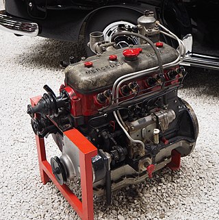
The Mercedes-Benz OM 138 is a diesel engine manufactured by Daimler-Benz. In total, 5,719 units were produced between 1935 and 1940. It was the first diesel engine especially developed and made for a passenger car. The first vehicle powered by the OM 138 was the Mercedes-Benz W 138. The light Mercedes-Benz trucks L 1100 and L 1500 as well as the bus O 1500 were also offered with the OM 138 as an alternative to the standard Otto engine.
The De Dion-Bouton 130 hp aircraft engine, also referred to as De Dion-Bouton 12B, was a twelve-cylinder, air cooled vee aircraft engine that has been built by De Dion-Bouton.
The Suzuki A100 is a Japanese motorcycle from the Suzuki Motor Corporation with production starting in 1966.Similar models were produced by Yamaha and Kawasaki with the YB100 & KH100 models, also with a single-cylinder two-stroke engine and rotary valve being examples.
Harry's Old Engine "Antique gas engine collection"–a wide variety of hit-and-miss engine manuals (different makes, different uses), each with a detailed, illustrated description page, some including audio clips of the engines running
This page is based on this Wikipedia article Text is available under the CC BY-SA 4.0 license; additional terms may apply. Images, videos and audio are available under their respective licenses.