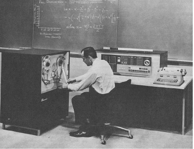
The IBM 1620 was a model of scientific minicomputer produced by IBM. It was announced on October 21, 1959,[1] and was then marketed as an inexpensive scientific computer.[2] After a total production of about two thousand machines, it was withdrawn on November 19, 1970. Modified versions of the 1620 were used as the CPU of the IBM 1710 and IBM 1720 Industrial Process Control Systems (making it the first digital computer considered reliable enough for real-timeprocess control of factory equipment).[1]
Being variable-word-length decimal, as opposed to fixed-word-length pure binary, made it an especially attractive first computer to learn on– and hundreds of thousands of students had their first experiences with a computer on the IBM 1620.
Core memory cycle times were 20 microseconds for the (earlier) Model I, 10 microseconds for the Model II (about a thousand times slower than typical computer main memory in 2006). The Model II was introduced in 1962.[3]
Architecture
Memory
The IBM 1620 Model I was a variable "word" length decimal (BCD) computer using magnetic-core memory. The Model I core could hold 20,000 decimal digits with each digit stored in six bits.[4][3] More memory could be added with the IBM 1623 Storage Unit, Model 1 which held 40,000 digits, or the 1623 Model 2 which held 60,000.[1]
The Model II deployed the IBM 1625 core-storage memory unit,[5][6] whose memory cycle time was halved by using faster cores, compared to the Model I's (internal or 1623 memory unit): to 10μs (i.e., the cycle speed was raised to 100kHz).
While the five-digit addresses of either model could have addressed 100,000 decimal digits, no machine larger than 60,000 decimal digits was ever marketed.[7]
Memory access
Memory was accessed two decimal digits at the same time (even-odd digit pair for numeric data or one alphameric character for text data). Each decimal digit was six bits, composed of an odd parity Check bit, a Flag bit, and four BCD bits for the value of the digit in the following format:[8]
C F 8 4 2 1
The Flag bit had several uses:
In the least significant digit it was set to indicate a negative number (signed magnitude).
It was set to mark the most significant digit of a number (word mark).
In the least significant digit of five-digit addresses it was set for indirect addressing (an option on the Model I, standard on the 1620 Model II). Multi-level indirection[1] could be used (the machine could even be put into an infinite indirect addressing loop).
In the middle three digits of five-digit addresses (on the 1620 II) they were set to select one of seven index registers.
In addition to the valid BCD digit values there were three special digit values (these could not be used in calculations):
C F 8 4 2 1 1 0 1 0 –Record Mark (right most end of record, prints as a double dagger symbol, ‡) 1 1 0 0 – Numeric Blank (blank for punched card output formatting) 1 1 1 1 –Group Mark (right most end of a group of records for disk I/O)
Instructions were fixed length (12 decimal digits), consisting of a two-digit "op code", a five-digit "P Address" (usually the destination address), and a five-digit "Q Address" (usually the source address or the source immediate value). Some instructions, such as the B (branch) instruction, used only the P Address, and later smart assemblers included a "B7" instruction that generated a seven-digit branch instruction (op code, P address, and one extra digit because the next instruction had to start on an even-numbered digit).
Fixed-point data "words" could be any size from two decimal digits up to all of memory not used for other purposes.
Floating-point data "words" (using the hardware floating-point option) could be any size from 4 decimal digits up to 102 decimal digits (2 to 100 digits for the mantissa and two digits for the exponent).
The Fortran II compiler offered limited access to this flexibility via a "Source Program Control Card" preceding the Fortran source in a fixed format:
*ffkks
The * in column one, ff the number of digits for the mantissa of floating-point numbers (allowing 02 to 28), kk the number of digits for fixed-point numbers (allowing 04 to 10) and s is to specify the memory size of the computer to run the code if not the current computer: 2, 4, or 6 for memories of 20,000 or 40,000 or 60,000 digits.
The machine had no programmer-accessible registers: all operations were memory to memory (including the index registers of the 1620 II).
Flagged Record Mark On tape a WN punches EOL instead!
EOL
‡
(Stop, WN) ‡ (DN)
(Stop)
‡
E
E (WN) 082 (DN)
0-2-8
0-2-8
C82
End of line Tape only. Note: In memory is a Record Mark!
GM
(Stop, WN) (DN)
(Stop)
G
08421
08421
0-7-8
0-7-8
C8421
Group Mark
flag GM
(Stop, WN) (DN)
(Stop)
X
X8421
X8421
12-7-8
12-7-8
F8421
Flagged Group Mark
NB
@
@
@
C84
C84
4-8
C84
Numeric Blank
flag NB
@
@
*
X84
X84
11-4-8
F84
Flagged Numeric Blank
Invalid character
The Model I used the Cyrillic characterЖ (pronounced zh) on the typewriter as a general-purpose invalid character with correct parity (invalid parity being indicated with an overstrike "–"). In some 1620 installations it was called a SMERSH, as used in the James Bond novels that had become popular in the late 1960s. The Model II used a new character ❚ (called "pillow") as a general purpose invalid character with correct parity.
Architectural difficulties
Although the IBM 1620's architecture was very popular in the scientific and engineering community, computer scientist Edsger Dijkstra pointed out several flaws in its design in EWD37, "A review of the IBM 1620 data processing system".[9] Among these are that the machine's Branch and Transmit instruction together with Branch Back allow only one level of nested subroutine call, forcing the programmer of any code with more than one level to decide where the use of this "feature" would be most effective. He also showed how the machine's paper tape reading support could not properly read tapes containing record marks, since record marks are used to terminate the characters read in storage. One effect of this is that the 1620 cannot duplicate a tape with record marks in a straightforward way: when the record mark is encountered, the punch instruction punches an EOL character instead and terminates. However this was not a crippling problem:
the data can be copied to the end of memory and punched verbatim with a DN instruction instead of WN
Most 1620 installations used the more convenient punched card input/output,[10] rather than paper tape.
The successor to the 1620, the IBM 1130,[11] was based on a totally different, 16-bit binary architecture. (The 1130 line retained one 1620 peripheral, the IBM 1627 drum plotter.)
The Monitors provided disk based versions of 1620SPSIId, FORTRANIId as well as a DUP (Disk Utility Program). Both Monitor systems required 20,000 digits or more of memory and one or more 1311 disk drives.
A collection of IBM1620 related manuals in PDF format exists at bitsavers.[13]
1620 non-decimal arithmetic
Since the Model I used in-memory lookup tables for addition/subtraction,[14] limited bases (5 to 9) unsigned number arithmetic could be performed by changing the contents of these tables, but noting that the hardware included a ten's complementer for subtraction (and addition of oppositely signed numbers).
To do fully signed addition and subtraction in bases 2 to 4 required detailed understanding of the hardware to create a "folded" addition table that would fake out the complementer and carry logic.
Also the addition table would have to be reloaded for normal base 10 operation every time address calculations were required in the program, then reloaded again for the alternate base. This made the "trick" somewhat less than useful for any practical application.
Since the Model II had addition and subtraction fully implemented in hardware, changing the table in memory could not be used as a "trick" to change arithmetic bases. However an optional special feature in hardware for octal input/output, logical operations, and base conversion to/from decimal was available.
Although bases other than 8 and 10 were not supported, this made the Model II very practical for applications that needed to manipulate data formatted in octal by other computers (e.g., the IBM7090).
Model I
Drawing showing internal layout of "gates"
The IBM 1620 Model I (commonly called "1620" from 1959 until the 1962 introduction of the Model II) was the original. It was produced as inexpensively as possible, to keep the price low.
It lacked conventional ALU hardware: arithmetic was done by memory table lookup. Addition and subtraction used a 100-digit table (at address 00300..00399). Multiplication used a 200-digit table (at address 00100..00299).[15]:p.4.4 The basic machine used software subroutines for division, although optional divide hardware could be installed that used a repeated subtraction algorithm. Floating-point arithmetic instructions were an available option (if the divide option was installed).
The first 20,000 decimal digits of magnetic-core memory were internal to the CPU itself (which reduced the floor space requirements of the basic system). Expansion to either 40,000 or 60,000 decimal digits required the addition of an IBM 1623 Memory unit. The memory cycle time was 20μs (that is, the memory speed was 50kHz = 1/20 of a MHz). A Memory Address Register Storage (MARS)[15] Core memory read, clear, or write operation took 2μs and each write operation was automatically (but not necessarily immediately) preceded by a read or clear operation of the same "register(s)" during the 20μs memory cycle.
The central processor clock speed was 1MHz, which was divided by 20 by a 10-position ring counter to provide the system timing and control signals. Instructions took eight memory cycles (160μs) to fetch and a variable number of memory cycles to execute. Indirect addressing[1] added four memory cycles (80μs) for each level of indirection.
The IBM 1620 Model II (commonly called simply the Model II) was a vastly improved implementation, compared to the original Model I. The Model II was introduced in 1962.
It had basic ALU hardware for addition and subtraction, but multiplication was still done by in-core memory table lookup, using a 200-digit table (at address 00100..00299). Memory addresses at address 00300..00399 were freed by the replacement of the addition table with hardware, resulting in storage of two selectable "bands" of seven five-digit index registers.
Rather than being an available option, as in the Model I, the divide hardware using a repeated subtraction algorithm, was built in. Floating-point arithmetic was an available option, as were octal input/output, logical operations, and base conversion to/from decimal instructions.
The entire core memory was in the IBM 1625 memory unit. Memory cycle time was halved compared to the Model I's (internal or 1623 memory unit), to 10μs (i.e., the cycle speed was raised to 100kHz) by using faster cores.[6] A Memory Address Register Storage (MARS) core memory read, clear, or write operation took 1.5μs and each write operation was automatically (but not necessarily immediately) preceded by a read or clear operation of the same "register(s)" during the 10μs memory cycle.
The processor clock speed was also doubled, to 2MHz, which was still divided by 20 by a 10 position ring counter to provide the system timing/control signals. The fetch/execute mechanism was completely redesigned, optimizing the timing and allowing partial fetches when the P or Q fields were not needed. Instructions took either 1, 4, or 6 memory cycles (10μs, 40μs, or 60μs) to fetch and a variable number of memory cycles to execute. Indirect addressing[1] added three memory cycles (30μs) for each level of indirection. Indexed addressing added five memory cycles (50μs) for each level of indexing. Indirect and indexed addressing could be combined at any level of indirection or indexing.[17]
Models I and II consoles
While the Lower console for both the Model 1[18] and the Model 2[19] IBM 1620 systems had the same lamps and switches, the Upper console of the pair were partly different.
Upper console
Model I (Upper console)
#Lamps
Model II (Upper console)
#Lamps
Instruction and Execute Cycle
60
Control Gates
60
Control Gates
35
Input-Output
35
Input-Output
15
Inst & Exec Cycle
15
The balance of the Upper console was the same on both models:
Check Condition status lamps/switches– 15 lamps & 5 toggle switches
Program Switches– 4 toggle switches
Console operator lights/switches– 13 lights, 1 power switch, and 12 buttons
Console typewriter
The Model I console typewriter was a modified Model B1, interfaced by a set of relays, and it typed at only 10 characters per second.
There were a set of instructions that wrote to the typewriter, or read from it. The general RN (read numeric) and WN (write numeric) instructions had assembly language mnemonics that supplied the "device" code in the second address field, and the control code in the low-order digit of the second address field.
WNTY: Write Numeric TYpewriter: each memory location contained a 6-bit character in the range of 000000 to 001001; with this instruction, each memory location was rendered as one of the characters "0" through "9".
WATY: Write Alphanumeric TYpewriter: each pair of memory locations contained two 6-bit digits that appeared on the typewriter as one of the 64 characters that could appear.
RNTY: Read Numeric TYpewriter: read a numeric value from the typewriter keyboard
RATY: Read Alphanumeric TYpewriter: read a character from the keyboard and store as a two-digit alphanumeric character
TBTY: TaBTYpewriter. Tabs had to be set manually, so this instruction was rarely used.
RCTY: Return Carriage TYpewriter: Caused the typewriter to do what we now call a CR/LF sequence.
To simplify input and output, there were two instructions:
TNS: Transmit Numeric Strip: Converts a two-digit alphanumeric representation of "0" to "9" to a single-digit representation
TNF: Transmit Numeric Fill: Converts a single-digit representation of digits to a sequence to two-digit alphanumeric sequence that represented "0" through "9"
The Model II used a modified Selectric typewriter, which could type at 15.5cps– a 55% improvement.
IBM 1405– Disk Drive available as RPQ (request price quotation)
The standard "output" mechanism for a program was to punch cards, which was faster than using the typewriter. These punched cards were then fed through an IBM 407 mechanical calculator which could be programmed to print two cards, thus being able to use the additional print columns available on the 407. All output was synchronous, and the processor paused while the Input/Output (I/O) device produced the output, so the typewriter output could completely dominate program running time.
A faster output option, the IBM 1443 printer was introduced May 6, 1963,[22] and its 150–600 lines/minute capability was available for use with either model of the 1620.[23][24]
It could print either 120 or 144 columns. The character width was fixed, so it was the paper size that changed; the printer printed 10 characters to the inch, so a printer could print a maximum of 12 inches or 14.4 inches of text. In addition, the printer had a buffer, so the I/O delay for the processor was reduced. However, the print instruction would block if the line had not completed.
Operating procedures
The "operating system" for the computer constituted the human operator, who would use controls on the computer console, which consisted of a front panel and typewriter, to load programs from the available bulk storage media such as decks of punched cards or rolls of paper tape that were kept in cabinets nearby. Later, the model 1311 disc storage device attached to the computer enabled a reduction in the fetch and carry of card decks or paper tape rolls, and a simple "Monitor" operating system could be loaded to help in selecting what to load from disc.[20][25]
A standard preliminary was to clear the computer memory of any previous user's detritus– being magnetic cores, the memory retained its last state even if the power had been switched off. This was effected by using the console facilities to load a simple computer program via typing its machine code at the console typewriter, running it, and stopping it. This was not challenging as only one instruction was needed such as 160001000000, loaded at address zero and following. This meant transmit field immediate (the 16: two-digit op-codes) to address 00010 the immediate constant field having the value 00000 (five-digit operand fields, the second being from address 11 back to 7), decrementing source and destination addresses until such time as a digit with a "flag" was copied. This was the normal machine code means of copying a constant of up to five digits. The digit string was addressed at its low-order end and extended through lower addresses until a digit with a flag marked its end. But for this instruction, no flag would ever be found because the source digits had shortly before been overwritten by digits lacking a flag. Thus the operation would roll around memory (even overwriting itself) filling it with all zeroes until the operator grew tired of watching the roiling of the indicator lights and pressed the Instant Stop - Single Cycle Execute button. Each 20,000 digit module of memory took just under one second to clear. On the 1620 II this instruction would NOT work (due to certain optimizations in the implementation). Instead there was a button on the console called Modify which when pressed together with the Check Reset button, when the computer was in Manual mode, would set the computer in a mode that would clear all of memory in a tenth of one second regardless of how much memory you had; when you pressed Start. It also stopped automatically when memory was cleared, instead of requiring the operator to stop it.
Other than typing machine code at the console, a program could be loaded via either the paper tape reader, the card reader, or any disk drive. Loading from either tape or disk required first typing a "bootstrap" routine on the console typewriter.
The card reader made things easier because it had a special Load button to signify that the first card was to be read into the computer's memory (starting at address 00000) and executed (as opposed to just starting the card reader, which then awaits commands from the computer to read cards)– this is the "bootstrap" process that gets into the computer just enough code to read in the rest of the code (from the card reader, or disc, or...) that constitutes the loader that will read in and execute the desired program.
Programs were prepared ahead of time, offline, on paper tape or punched cards. But usually the programmers were allowed to run the programs personally, hands-on, instead of submitting them to operators as was the case with mainframe computers at that time. And the console typewriter allowed entering data and getting output in an interactive fashion, instead of just getting the normal printed output from a blind batch run on a pre-packaged data set. As well, there were four program switches on the console whose state a running program could test and so have its behavior directed by its user. The computer operator could also stop a running program (or it may come to a deliberately programmed stop) then investigate or modify the contents of memory: being decimal-based, this was quite easy; even floating-point numbers could be read at a glance. Execution could then be resumed, from any desired point. Aside from debugging, scientific programming is typically exploratory, by contrast to commercial data processing where the same work is repeated on a regular schedule.
Console
IBM 1620 Memory address register display selector switch
The most important items on the 1620's console were a pair of buttons labeled Insert & Release, and the console typewriter.
Insert – Pressing this key with the computer in Manual mode reset the program counter (in the MARS core memory) to zero, switched the computer into Automatic and Insert modes, and simulated the execution of a Read Numeric from Typewriter to address zero (unlocked the typewriter keyboard, shifted the typewriter into numeric mode). Note: unlike a real Read Numeric from Typewriter, Insert mode would force a Release after 100 digits had been typed to prevent overwriting the arithmetic tables.
Release – Pressing this key while doing a Read from the Typewriter terminated the Read, switched the computer into Manual mode, and locked the typewriter keyboard.
The typewriter is used for operator input/output, both as the main console control of the computer and for program controlled input/output. Later models of the typewriter had a special key marked R-S that combined the functions of the console Release & Start buttons (this would be considered equivalent to an Enter key on a modern keyboard). Note: several keys on the typewriter did not generate input characters, these included Tab and Return (the 1620s alphameric and numeric BCD character sets lacked character codes for these keys).
The next most important items on the console were the buttons labeled Start, Stop-SIE, and Instant Stop-SCE.
Start – Pressing this key with the computer in Manual mode switched the computer to Automatic mode (causing the computer to begin executing at the address in the program counter).
Stop-SIE – Pressing this key with the computer in Automatic mode switched the computer to Manual mode when the currently executing instruction completes. Pressing this key with the computer in Manual mode switched the computer into Automatic mode for one instruction.
Instant Stop-SCE – Pressing this key with the computer in Automatic mode switched the computer into Automatic/Manual mode at the end of the current memory cycle. Pressing this key with the computer in Manual or Automatic/Manual mode switched the computer into Automatic/Manual mode and executed one memory cycle.
For program debugging there were the buttons labeled Save & Display MAR.
Save – Pressing this key with the computer in Manual mode saved the program counter into another register in the MARS core memory and activated Save mode.
When a Branch Back instruction was executed in Save mode, it copied the saved value back to the program counter (instead of copying the return address register as it normally did) and deactivated Save mode.
This was used during debugging to remember where the program had been stopped to allow it to be resumed after the debugging instructions that the operator had typed on the typewriter had finished. Note: the MARS register used to save the program counter in was also used by the Multiply instruction, so this instruction and the Save mode were incompatible! However, there was no need to use multiply in debugging code, so this was not considered to be a problem.
Display MAR – Pressing this key with the computer in Manual mode displayed the selected MARS register and the contents of the memory at that address on the console lamps.
"Breakpoint" procedure
Notes
Press Stop-SIE
Stop the computer at the end of the current instruction.
Press Save
Save the address to resume execution at.
Press Insert
Unlocks typewriter keyboard and shifts into numeric mode.
Type 35xxxxx0010036xxxxx0010042
xxxxx is the address that you plan to set the breakpoint at.
Press Release
Locks typewriter keyboard.
Press Start
Begin execution. Allow the 12 digit instruction to print out.
Press Release
Stops the Dump Numeric.
Press Start
Begin execution.
Type 48
Replace the opcode of the instruction to "break" at with a Halt opcode.
Press Release
Locks typewriter keyboard.
Press Start
Resume execution. Wait until the computer halts at the "breakpoint".
Press Insert
Unlocks typewriter keyboard and shifts into numeric mode.
Type 36xxxxx0010049xxxxx
xxxxx is the address that you previously set the breakpoint at, you are now going to clear it.
Press Release
Locks typewriter keyboard.
Press Start
Begin execution.
Type oo
oo is the 2 digit opcode the original 12 digit instruction previously printed out.
Press Release
Locks typewriter keyboard.
Press Stop-SIE
The machine is now ready to resume execution from the location of the (now cleared) "breakpoint". You can perform any required debugging actions now, before continuing.
All of main memory could be cleared from the console by entering and executing a transfer instruction from address to address +1, this would overwrite any word mark, that would normally stop a transfer instruction, and wrap around at the end of memory. After a moment, pressing Stop would stop the transfer instruction and memory would be cleared.
IBM 1621/1624 Paper Tape reader/punch
User holding paper tape at the IBM 1620 with the IBM 1621 paper tape reader in background, IBM headquarters, White Plains, NY, 1961
The IBM 1621 Paper Tape Reader could read a maximum of 150 characters per second; The IBM 1624 Paper Tape Punch could output a maximum of 15 characters/second.[1]
Both units:
could handle eight-channel paper tape
performed self-checking to ensure accuracy
accommodated both numerical and alphabetic information in single-character coding.
The 1621 Tape Reader and 1624 Tape Punch included controls for:
Power switch – If "on" the unit reader is powered up when the CPU is powered on.
Reel-Strip switch – This switch selects whether Reels or Strips of paper tape are used.
Reel power key – Applies power to the supply and takeup Reels to position the tape for reading and places the reader in ready state.
Non-process runout key – Feeds tape until the reader is empty and takes the reader out of ready state.
Bootstrap procedure
Notes
Press Insert
Unlocks typewriter keyboard and shifts into numeric mode.
Type 36xxxxx0030049yyyyy
xxxxx is the address to load the tape into. yyyyy is the address to begin execution.
The 1622's controls were divided into three groups: 3 punch control rocker switches, 6 buttons, and 2 reader control rocker switches.
Punch Rocker switches:
Punch Off/Punch On – This rocker turned the punch mechanism off or on.
Select No-Stop/Select Stop – This rocker selected if mispunched cards (deposited in the punch error select stacker instead of the normal punch stacker) let the punch continue or caused a check stop.
Non-Process Runout – This rocker with the punch hopper empty, "ranout" remaining cards from the punch mechanism.
Buttons:
Start punch – Pressing this key with the punch idle and on, started the punch. The computer could now punch cards.
Stop punch – Pressing this key with the punch active, stopped the punch.
Check Reset – Pressing this key reset all "error check" conditions in the reader and punch.
Load – Pressing this key with the reader idle and on and the computer in Manual mode started the reader, reset the program counter (in the MARS core memory) to zero, read one card into the reader's buffer and checked the card for errors, and simulated the execution of a Read Numeric from Card Reader to address zero (reading the 80 characters of the reader's buffer into memory addresses 00000 to 00079), then switched the computer into Automatic mode (starting execution at the address in the program counter).
Stop reader – Pressing this key with the reader active, stopped the reader.
Start reader – Pressing this key with the reader idle and on, started the reader and read one card into the reader's buffer and checked the card for errors. The computer could now read cards.
Reader Rocker switches:
Non-Process Runout – This rocker with the read hopper empty, "ranout" remaining cards from the reader mechanism.
Reader Off/Reader On – This rocker turned the reader mechanism off or on.
Bootstrap procedure
Notes
Press Load
Disk drives
IBM 1311 Disk Drives– Model 2 (Slave) & Model 3 (Master), attached to an IBM 1620 II
Module light – This light shows the drive number. When it lights the drive is ready for access.
Compare-Disable key-switch – When this (Master only) switch is in the ON position and the Write Address button is pressed a full track write may be performed without comparing addresses. Used to format disk packs.
Select Lock light – When this (Master only) lights one or more of the drives has malfunctioned. No disk access can be performed.
Write Address button/light – This (Master only) key controls writing sector addresses. Pressing it toggles this enable and turns its light on/off.
Enable-Disable toggle-switch – This switch enables or disables access to the drive. If this switch is disabled on the Master, all drives are disabled regardless of the state of their own switches. Also controls the disk usage time meter(s).
Start Stop button – Pressing this key starts or stops the disk drive motor. The motor must be stopped to open the lid and change disk packs.
Bootstrap procedure
Notes
Press Insert
Unlocks typewriter keyboard and shifts into numeric mode.
Type 3400032007013600032007024902402 x y1963611300102
x– Specifies source of Monitor control cards: 1=typewriter, 3=paper tape, 5=cards y– Specifies disk drive on which Monitor resides: 1, 3, 5, 7 02402 is the address of the entry point of the Monitor program.
Press Release
Locks typewriter keyboard.
Press Start
Begin execution.
Restart procedure
Notes
Press Insert
Unlocks typewriter keyboard and shifts into numeric mode.
Type 490225FLG6
02256̅ is the address of the location containing the address of the restart point of the Monitor program. Note: this procedure assumes the Monitor is already loaded in memory
Press Release
Locks typewriter keyboard.
Press Start
Begin execution.
General
The FORTRAN II compiler and SPS assembler were somewhat cumbersome to use[26][27] by modern standards, however, with repetition, the procedure soon became automatic and you no longer thought about the details involved.
FORTRAN II compilation procedure
Notes
Set the Program Switches as follows:
OFF (No Source listing)
OFF (No Batch compilation)
OFF (Source is entered from cards)
OFF (Only used if 3 is ON)
Pass I options
Set Overflow Check switch to Program and all others to Stop
Press Reset
Load blank cards (face down 12-edge first) into the Punch hopper then press Punch Start
Load Pass I of the compiler (face down 9-edge first) into the Read hopper then press Load
Wait for Pass I to load and print on the typewriter "ENTER SOURCE PROGRAM, PRESS START"
Remove Pass I of the compiler from the Read stacker
Load the program source deck (face down 9-edge first) into the Read hopper then press Start
Wait for Pass I to complete and print on the typewriter "TURN SW 1 ON FOR SYMBOL TABLE, PRESS START"
Turn Program Switch 1 OFF then press Start
If a symbol table listing is desired for debugging, turn Program Switch 1 ON instead. The symbol table listing will be printed on the typewriter. Wait for Pass I to print on the typewriter "END OF PASS 1"
Set the Program Switches as follows:
OFF (No statement number/address listing)
OFF (Not used)
OFF (No trace for IF statements)
OFF (No trace for arithmetic statements)
Pass II options
Set Overflow Check switch to Program and all others to Stop
Press Reset
Load blank cards (face down 12-edge first) into the Punch hopper then press Punch Start
Load Pass II of the compiler (face down 9-edge first) into the Read hopper then press Load
Wait for Pass II to load
Remove Pass II of the compiler from the Read stacker
Remove the intermediate output of Pass I from the Punch stacker, then load it (face down 9-edge first) into the Read hopper and press Reader Start then Start
Wait for Pass II to complete and print on the typewriter "SW 1 ON TO PUNCH SUBROUTINES, PRESS START"
Remove the intermediate output from the Reader stacker
Turn Program Switch 1 ON, load the Subroutine deck (face down 9-edge first) into the Read hopper, then press Reader Start then Start
Wait for Pass II to print on the typewriter "END OF PASS II"
Remove the Subroutine deck from the Reader stacker and the completed Object deck from the Punch stacker
GOTRAN was much simpler to use, as it directly produced an executable in memory. However it was not a complete FORTRAN implementation.
To improve this various third-party FORTRAN compilers were developed. One of these was developed by Bob Richardson,[28][29] a programmer at Rice University, the FLAG (FORTRAN Load-and-Go) compiler. Once the FLAG deck had been loaded, all that was needed was to load the source deck to get directly to the output deck; FLAG stayed in memory, so it was immediately ready to accept the next source deck. This was particularly convenient for dealing with many small jobs. For instance, at Auckland University a batch job processor for student assignments (typically, many small programs not requiring much memory) chugged through a class lot rather faster than the later IBM 1130 did with its disk-based system. The compiler remained in memory, and the student's program had its chance in the remaining memory to succeed or fail, though a bad failure might disrupt the resident compiler.
Later, disk storage devices were introduced, removing the need for working storage on card decks. The various decks of cards constituting the compiler and loader no longer need be fetched from their cabinets but could be stored on disk and loaded under the control of a simple disk-based operating system: a lot of activity becomes less visible, but still goes on.
Since the punch side of the card reader-punch did not edge-print the characters across the top of the cards, one had to take any output decks over to a separate machine, typically an IBM 557 Alphabetic Interpreter, that read each card and printed its contents along the top. Listings were usually generated by punching a listing deck and using an IBM 407 accounting machine to print the deck.
Most of the logic circuitry of the 1620 was a type of resistor–transistor logic (RTL) using "drift" transistors (a type of transistor invented by Herbert Kroemer in 1953) for their speed, that IBM referred to as Saturated Drift Transistor Resistor Logic (SDTRL). Other IBM circuit types used were referred to as: Alloy (some logic, but mostly various non-logic functions, named for the kind of transistors used), CTRL (another type of RTL, but slower than SDTRL), CTDL (a type of diode–transistor logic (DTL)), and DL (another type of RTL, named for the kind of transistor used, "drift" transistors). Typical logic levels of all these circuits (S Level) were high: 0V to -0.5V, low: -6V to -12V. Transmission line logic levels of SDTRL circuits (C Level) were high: 1V, low: -1V. Relay circuits used either of two logic levels (T Level) high: 51V to 46V, low: 16V to 0V or (W Level) high: 24V, low: 0V.
These circuits were constructed of individual discrete components mounted on single sided paper-epoxy printed circuit boards 2.5 by 4.5 inches (64 by 114 millimeters) with a 16-pin gold-plated edge connector, that IBM referred to as SMS cards (Standard Modular System). The amount of logic on one card was similar to that in one 7400 seriesSSI or simpler MSI package (e.g., 3 to 5 logic gates or a couple of flip-flops).
These boards were inserted into sockets mounted in door-like racks which IBM referred to as gates. The machine had the following "gates" in its basic configuration:
"Gate A"– Forward hinged gate that swings out the back for access, after "Gate B".
"Gate B"– Rear hinged gate that swings out the back for access.
"Gate C"– Slides out back for access. Console Typewriter interface. Mostly relay logic.
"Gate D"– Slides out back for access. Standard I/O interface.
There were two different types of core memory used in the 1620:
Main memory
Coincident Current X-Y Line addressing
20,000, 40,000, or 60,000 Digits
12-bit, even-odd Digit Pair
12 one-bit planes in each module, 1 to 3 modules
10,000 cores per plane
Memory Address Register Storage (MARS) memory
Word Line addressing
16 Words, minimum of eight used in basic configuration
Single Word read, multiple Word clear/write
24-bit, five-digit decimal Memory Address (no 8 - Ten Thousand bit stored)
1 plane
384 cores
The address decoding logic of the Main memory also used two planes of 100 pulse transformer cores per module to generate the X-Y Line half-current pulses.
There were two models of the 1620, each having totally different hardware implementations:
In 1958 IBM assembled a team at the Poughkeepsie, New York development laboratory to study the "small scientific market". Initially the team consisted of Wayne Winger (Manager), Robert C. Jackson, and William H. Rhodes.
Requirements and design
The competing computers in this market were the Librascope LGP-30 and the Bendix G-15; both were drum memory machines. IBM's smallest computer at the time was the popular IBM 650, a fixed word length decimal machine that also used drum memory. All three used vacuum tubes. It was concluded that IBM could offer nothing really new in that area. To compete effectively would require use of technologies that IBM had developed for larger computers, yet the machine would have to be produced at the least possible cost.
To meet this objective, the team set the following requirements:
Core memory
Restricted instruction set
No divide or floating-point instructions, use subroutines in the "general program package"
Wherever possible replace hardware with existing logical machine functions
No arithmetic circuits, use tables in core memory
Least expensive Input/Output possible
No punch cards, use paper tape
No printer, use operator's console typewriter
The prototype
The team expanded with the addition of Anne Deckman, Kelly B. Day, William Florac, and James Brenza. They completed the (codename) CADET prototype in the spring of 1959.
Meanwhile, the San Jose, California facility was working on a proposal of its own. IBM could only build one of the two and the Poughkeepsie proposal won because "the San Jose version is top of the line and not expandable, while your proposal has all kinds of expansion capability - never offer a machine that cannot be expanded".
IBM 1620 Model I Level A (prototype), as it appeared
in the IBM announcement of the machine.
Management was not entirely convinced that core memory could be made to work in small machines, so Gerry Ottaway was loaned to the team to design a drum memory as a backup. During acceptance testing by the Product Test Lab, repeated core memory failures were encountered and it looked likely that management's predictions would come true. However, at the last minute it was found that the muffin fan used to blow hot air through the core stack was malfunctioning, causing the core to pick up noise pulses and fail to read correctly. After the fan problem was fixed, there were no further problems with the core memory and the drum memory design effort was discontinued as unnecessary.
Transferred to San Jose for production
Following announcement of the IBM 1620 on October 21, 1959, due to an internal reorganization of IBM, it was decided to transfer the computer from the Data Processing Division at Poughkeepsie (large scale mainframe computers only) to the General Products Division at San Jose (small computers and support products only) for manufacturing.
Following transfer to San Jose, someone there jokingly suggested that the code name CADET actually stood for "Can't Add, Doesn't Even Try", referring to the use of addition tables in memory rather than dedicated addition circuitry (and SDTRL actually stood for "Sold Down The River Logic" became a common joke among the CEs). This stuck and became very well known among the user community.[30][31][32]
All flip-flops in the design were transistorized versions of the original Eccles-Jordan trigger circuit. While this machine was fully functional, it was found that the capacitor coupling used in these proved troublesome in the noisy signal environment of relays and timing cam driven switches used to drive the console typewriter. This necessitated a complete redesign of the machine to use S-R flip-flops instead (except for two triggers used to generate clocks for the S-R flip-flops). However usage of the term Trigger was retained in all the documentation when referring to a flip-flop, as it was IBM's conventional term (as alphamerics was their term for alphanumerics).
This is the only level using a one piece vertical control panel, when the design was transferred from Poughkeepsie to San Jose it was redesigned to the two piece angled control panel used on all production models.
Level B; first production.
This is the only level using a burnished aluminum lower control panel, later levels finished this panel with white.
Level C; introduction of 1622 card reader/punch.
Level D; introduction of 1311 disk drives and addition of optional "Gate J" containing disk control logic.
Level E; introduction of Floating-Point option.
Level F
Level G; introduction of Interrupt option (needed for IBM 1710).
Did not support BT & BB subroutines in interrupt code!
Disk control logic on "Gate J" logic merged into "Gate A" & "Gate B".
Made possible because much of logic was compacted using cards designed for the Model II.
Level H; improved Interrupt option that supported BT & BB subroutines in interrupt code.
Final version of the Model I.
Model II (no information on "Levels" available at this time)
The 1620 Model II introduced basic ALU hardware for addition and subtraction (making "Can't Add, Doesn't Even Try" no longer applicable) and index registers.
Model III
Work was begun on a 1620 Model III but the project was quickly canceled as IBM wanted to promote sales of their new System/360 and discontinue the old lines.
An IBM 1620 model II was used by Vearl N. Huff, NASA Headquarters (FOB 10B, Washington DC) to program a three-dimensional simulation in Fortran of the tethered Gemini capsule–Agena rocket module two-body problem at a time when it was not completely understood if it was safe to tether two objects together in space due to possible elastic tether induced collisions. The same computer was also used to simulate the orbits of the Gemini flights, producing printer-art charts of each orbit. These simulation were run over-night and the data examined the next day.[33]
In 1963 an IBM 1620 was installed at IIT Kanpur providing the kicker for India's software prowess.[34]
In 1964 at the Australian National University, Martin Ward used an IBM 1620 model I to calculate the order of the Janko group J1.[35]
A radio program was developed by DJ Rege Cordic for KDKA Pittsburgh, based on a baseball game simulator developed by John Burgeson of IBM and his brother, Paul, then an ensign in the U.S. Navy. This program was used in numerous demonstration events in the years 1960 to 1963 as an example of the power of computers to perform simulation exercises.
A similar arrangement was used in a late TV episode[39] and a movie[40] of The Man from U.N.C.L.E. to portray a THRUSH supercomputer.
Anecdotes
CADET
Many in the user community recall the 1620 being referred to as CADET, jokingly meaning "Can't Add, Doesn't Even Try", referring to the use of addition tables in memory rather than dedicated addition circuitry.[41]
See development history for an explanation of all three known interpretations of the machine's code name.
The internal code name CADET was selected for the machine. One of the developers says that this stood for "Computer with ADvanced Economic Technology", however others recall it as simply being one half of "SPACE - CADET", where SPACE was the internal code name of the IBM 1401 machine, also then under development.[citation needed]
↑Although there are descriptions of a single 100,000-digit machine, designed in the late 1960s, using heavily modified hardware.
↑"The main memory was logically arranged as 20,000 6-bit words. Each word comprised four BCD data bits, a "flag" bit, and an odd parity check bit. Though this was its logical arrangement, physically memory was a 100x100 array of 12-bit ferrite core words, which causes a few quirks in the instruction set. All instructions occupied 12 consecutive digits of memory, and were required to start at an even address so that the two-digit opcode could be read in one 12-bit physical word." "The IBM 1620 Model 1– Physics @ SMU".
↑Weik, Martin H. (Mar 1961). "IBM 1620". ed-thelen.org. A Third Survey of Domestic Electronic Digital Computing Systems.
↑"Multi-level indirection could be used (you could even put the machine in an infinite indirect addressing loop), and in the middle three digits of five-digit addresses (on the 1620 II) they were set to select one of seven index registers. Dan Ryan (2011). History of Computer Graphics. DLR Associates Series. ISBN978-1456751159.
↑"1963: On May 6, the IBM 1443 printer, for use with the IBM 1620 data processing system, makes its debut." "DPD chronology". 23 January 2003. Archived from the original on August 20, 2010.
↑This publication describes the IBM 1443 Printer as an on-line output unit for the 1620 Data Processing Systems, :Models 1 and. 2, and for the 1710 Control System. File No. 1620/1710-03. Form A26-5730-2
↑"... 2 million characters, the equivalent of approximately 25,000 punched cards or a fifth of a reel of magnetic tape."
↑User:Br6cycles3, in his/first and only edit to date (24 Feb 2019, 18:15) attempted to change the name in the article from Bob Richardson to Mike McCants and wrote in the summary: "Correct misattribution: I'm Bob Richardson and I know the programmer was actually Mike McCants."
↑The IBM 1316 was the removable disk pack to the IBM 1311 disk drive of the IBM 1620, which explains the following: "“The Man from U.N.C.L.E.” movie's full of technological anachronisms ... Back in 1963, when the movie took place, there were disk packs available like the 10-pound IBM 1316." "The Man from U.N.C.L.E." movie's full of technological anachronisms".
This page is based on this Wikipedia article Text is available under the CC BY-SA 4.0 license; additional terms may apply. Images, videos and audio are available under their respective licenses.