
In electronics, a comparator is a device that compares two voltages or currents and outputs a digital signal indicating which is larger. It has two analog input terminals and and one binary digital output . The output is ideally
Transistor–transistor logic (TTL) is a logic family built from bipolar junction transistors. Its name signifies that transistors perform both the logic function and the amplifying function, as opposed to earlier resistor–transistor logic (RTL) and diode–transistor logic (DTL).
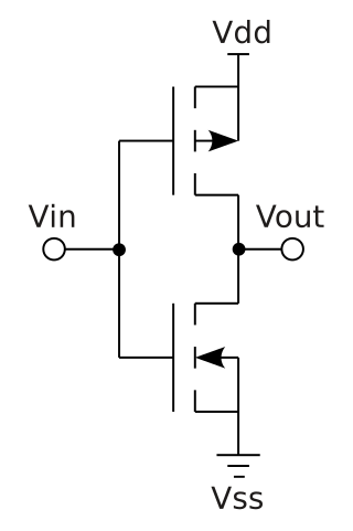
Complementary metal–oxide–semiconductor is a type of metal–oxide–semiconductor field-effect transistor (MOSFET) fabrication process that uses complementary and symmetrical pairs of p-type and n-type MOSFETs for logic functions. CMOS technology is used for constructing integrated circuit (IC) chips, including microprocessors, microcontrollers, memory chips, and other digital logic circuits. CMOS technology is also used for analog circuits such as image sensors, data converters, RF circuits, and highly integrated transceivers for many types of communication.

In digital logic, an inverter or NOT gate is a logic gate which implements logical negation. It outputs a bit opposite of the bit that is put into it. The bits are typically implemented as two differing voltage levels.

The 4000 series is a CMOS logic family of integrated circuits (ICs) first introduced in 1968 by RCA. It was slowly migrated into the 4000B buffered series after about 1975. It had a much wider supply voltage range than any contemporary logic family. Almost all IC manufacturers active during this initial era fabricated models for this series. Its naming convention is still in use today.

The 7400 series is a popular logic family of transistor–transistor logic (TTL) integrated circuits (ICs).
In computer engineering, a logic family is one of two related concepts:
A general-purpose input/output (GPIO) is an uncommitted digital signal pin on an integrated circuit or electronic circuit board which may be used as an input or output, or both, and is controllable by software.

IC power-supply pins denote a voltage and current supply terminals in electric, electronics engineering, and in Integrated circuit design. Integrated circuits (ICs) have at least two pins that connect to the power rails of the circuit in which they are installed. These are known as the power-supply pins. However, the labeling of the pins varies by IC family and manufacturer. The double subscript notation usually corresponds to a first letter in a given IC family (transistors) notation of the terminals.
The OR gate is a digital logic gate that implements logical disjunction. The OR gate returns true if any of its inputs are true; otherwise it returns false. The input and output states are normally represented by different voltage levels.
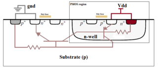
In electronics, a latch-up is a type of short circuit which can occur in an integrated circuit (IC). More specifically, it is the inadvertent creation of a low-impedance path between the power supply rails of a MOSFET circuit, triggering a parasitic structure which disrupts proper functioning of the part, possibly even leading to its destruction due to overcurrent. A power cycle is required to correct this situation.
XOR gate is a digital logic gate that gives a true output when the number of true inputs is odd. An XOR gate implements an exclusive or from mathematical logic; that is, a true output results if one, and only one, of the inputs to the gate is true. If both inputs are false (0/LOW) or both are true, a false output results. XOR represents the inequality function, i.e., the output is true if the inputs are not alike otherwise the output is false. A way to remember XOR is "must have one or the other but not both".
The NAND Boolean function has the property of functional completeness. This means that any Boolean expression can be re-expressed by an equivalent expression utilizing only NAND operations. For example, the function NOT(x) may be equivalently expressed as NAND(x,x). In the field of digital electronic circuits, this implies that it is possible to implement any Boolean function using just NAND gates.
The XNOR gate is a digital logic gate whose function is the logical complement of the Exclusive OR (XOR) gate. It is equivalent to the logical connective from mathematical logic, also known as the material biconditional. The two-input version implements logical equality, behaving according to the truth table to the right, and hence the gate is sometimes called an "equivalence gate". A high output (1) results if both of the inputs to the gate are the same. If one but not both inputs are high (1), a low output (0) results.
In integrated circuit design, dynamic logic is a design methodology in combinational logic circuits, particularly those implemented in metal–oxide–semiconductor (MOS) technology. It is distinguished from the so-called static logic by exploiting temporary storage of information in stray and gate capacitances. It was popular in the 1970s and has seen a recent resurgence in the design of high-speed digital electronics, particularly central processing units (CPUs). Dynamic logic circuits are usually faster than static counterparts and require less surface area, but are more difficult to design. Dynamic logic has a higher average rate of voltage transitions than static logic, but the capacitive loads being transitioned are smaller so the overall power consumption of dynamic logic may be higher or lower depending on various tradeoffs. When referring to a particular logic family, the dynamic adjective usually suffices to distinguish the design methodology, e.g. dynamic CMOS or dynamic SOI design.
In digital circuits, a logic level is one of a finite number of states that a digital signal can inhabit. Logic levels are usually represented by the voltage difference between the signal and ground, although other standards exist. The range of voltage levels that represent each state depends on the logic family being used. A logic-level shifter can be used to allow compatibility between different circuits.
PMOS or pMOS logic is a family of digital circuits based on p-channel, enhancement mode metal–oxide–semiconductor field-effect transistors (MOSFETs). In the late 1960s and early 1970s, PMOS logic was the dominant semiconductor technology for large-scale integrated circuits before being superseded by NMOS and CMOS devices.
HCMOS is the set of specifications for electrical ratings and characteristics, forming the 74HC00 family, a part of the 7400 series of integrated circuits.