Parasitic extraction

Last updated

In electronic design automation, parasitic extraction is calculation of the parasitic effects in both the designed devices and the required wiring interconnects of an electronic circuit: parasitic capacitances, parasitic resistances and parasitic inductances, commonly called parasitic devices, parasitic components, or simply parasitics.

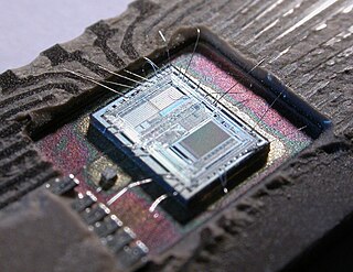
Electronic design automation (EDA), also referred to as electronic computer-aided design (ECAD), is a category of software tools for designing electronic systems such as integrated circuits and printed circuit boards. The tools work together in a design flow that chip designers use to design and analyze entire semiconductor chips. Since a modern semiconductor chip can have billions of components, EDA tools are essential for their design.

In integrated circuits (ICs), interconnects are structures that connect two or more circuit elements together electrically. The design and layout of interconnects on an IC is vital to its proper function, performance, power efficiency, reliability, and fabrication yield. The material interconnects are made from depends on many factors. Chemical and mechanical compatibility with the semiconductor substrate, and the dielectric in between the levels of interconnect is necessary, otherwise barrier layers are needed. Suitability for fabrication is also required; some chemistries and processes prevent integration of materials and unit processes into a larger technology (recipe) for IC fabrication. In fabrication, interconnects are formed during the back-end-of-line after the fabrication of the transistors on the substrate.

Electronic circuit electrical circuit with active components such as transistors, valves and integrated circuits; electrical network that contains active electronic components, generally nonlinear and require complex design and analysis tools

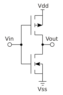
An electronic circuit is composed of individual electronic components, such as resistors, transistors, capacitors, inductors and diodes, connected by conductive wires or traces through which electric current can flow. To be referred to as electronic, rather than electrical, generally at least one active component must be present. The combination of components and wires allows various simple and complex operations to be performed: signals can be amplified, computations can be performed, and data can be moved from one place to another.

Contents

The major purpose of parasitic extraction is to create an accurate analog model of the circuit, so that detailed simulations can emulate actual digital and analog circuit responses. Digital circuit responses are often used to populate databases for signal delay and loading calculation such as: timing analysis; power analysis; circuit simulation; and signal integrity analysis. Analog circuits are often run in detailed test benches to indicate if the extra extracted parasitics will still allow the designed circuit to function.

Power optimization is the use of electronic design automation tools to optimize (reduce) the power consumption of a digital design, such as that of an integrated circuit, while preserving the functionality.

Signal integrity

Signal integrity or SI is a set of measures of the quality of an electrical signal. In digital electronics, a stream of binary values is represented by a voltage waveform. However, digital signals are fundamentally analog in nature, and all signals are subject to effects such as noise, distortion, and loss. Over short distances and at low bit rates, a simple conductor can transmit this with sufficient fidelity. At high bit rates and over longer distances or through various mediums, various effects can degrade the electrical signal to the point where errors occur and the system or device fails. Signal integrity engineering is the task of analyzing and mitigating these effects. It is an important activity at all levels of electronics packaging and assembly, from internal connections of an integrated circuit (IC), through the package, the printed circuit board (PCB), the backplane, and inter-system connections. While there are some common themes at these various levels, there are also practical considerations, in particular the interconnect flight time versus the bit period, that cause substantial differences in the approach to signal integrity for on-chip connections versus chip-to-chip connections.

Background

In early integrated circuits the impact of the wiring was negligible, and wires were not considered as electrical elements of the circuit. However below the 0.5-micrometre technology node resistance and capacitance of the interconnects started making a significant impact on circuit performance. [1] With shrinking process technologies inductance effects of interconnects became important as well.

Integrated circuit electronic circuit manufactured by lithography; set of electronic circuits on one small flat piece (or "chip") of semiconductor material, normally silicon

An integrated circuit or monolithic integrated circuit is a set of electronic circuits on one small flat piece of semiconductor material that is normally silicon. The integration of large numbers of tiny transistors into a small chip results in circuits that are orders of magnitude smaller, faster, and less expensive than those constructed of discrete electronic components. The IC's mass production capability, reliability, and building-block approach to circuit design has ensured the rapid adoption of standardized ICs in place of designs using discrete transistors. ICs are now used in virtually all electronic equipment and have revolutionized the world of electronics. Computers, mobile phones, and other digital home appliances are now inextricable parts of the structure of modern societies, made possible by the small size and low cost of ICs.

Micrometre one millionth of a metre

The micrometre or micrometer, also commonly known by the previous name micron, is an SI derived unit of length equalling 1×10⁻⁶ metre ; that is, one millionth of a metre.

Semiconductor device fabrication process used to create the integrated circuits that are present in everyday electrical and electronic devices

Semiconductor device fabrication is the process used to create the integrated circuits that are present in everyday electrical and electronic devices. It is a multiple-step sequence of photolithographic and chemical processing steps during which electronic circuits are gradually created on a wafer made of pure semiconducting material. Silicon is almost always used, but various compound semiconductors are used for specialized applications.

Major effects of interconnect parasitics include: signal delay, signal noise, IR drop (resistive component of voltage).

In signal processing, group delay is the time delay of the amplitude envelopes of the various sinusoidal components of a signal through a device under test, and is a function of frequency for each component. Phase delay, in contrast, is the time delay of the phase as opposed to the time delay of the amplitude envelope.

In integrated circuits, electrical power is distributed to the components of the chip over a network of conductors on the chip. Power network design includes the analysis and design of such networks. As in all engineering, this involves tradeoffs - the network must have adequate performance, be sufficiently reliable, but should not use more resources than required.

Interconnect capacitance extraction

Interconnect capacitance is calculated by giving the extraction tool the following information: the top view layout of the design in the form of input polygons on a set of layers; a mapping to a set of devices and pins (from a Layout Versus Schematic run), and a cross sectional understanding of these layers. This information is used to create a set of layout wires that have added capacitors where the input polygons and cross sectional structure indicate. The output netlist contains the same set of input nets as the input design netlist and adds parasitic capacitor devices between these nets.

The Layout Versus Schematic (LVS) is the class of electronic design automation (EDA) verification software that determines whether a particular integrated circuit layout corresponds to the original schematic or circuit diagram of the design.

Interconnect resistance extraction

Interconnect resistance is calculated by giving the extraction tool the following information: the top view layout of the design in the form of input polygons on a set of layers; a mapping to a set of devices and pins (from a Layout Versus Schematic run), and a cross sectional understanding of these layers including the resistivity of the layers. This information is used to create a set of layout sub.wires that have added resistance between various sub-parts of the wires. The above Interconnect Capacitance is divided and shared amongst the sub-nodes in a proportional way. Note that unlike Interconnect Capacitance, Interconnect Resistance needs to add sub-nodes between the circuit elements to place these parasitic resistors. This can greatly increase the size of the extracted output netlist and can cause additional simulation problems.

Interconnect inductance extraction

Tools and vendors

The tools fall into the following broad categories.


ANSYS Q3D Extractor

ANSYS Q3D Extractor uses method of moments (integral equations) and FEMs to compute capacitive, conductance, inductance and resistance matrices. It uses the fast multipole method (FMM) to accelerate the solution of the integral equations. Outputs from the solver include current and voltage distributions, CG and RL matrices. [2] [3]

FastCap, FastHenry

FastCap and FastHenry, from MIT (Massachusetts Institute of Technology) are two free parasitics extractor tools for capacitance, and inductance and resistance. Quoted in many scientific articles, they are considered golden references in their field. Source code, as well as Windows binary versions with viewer and editor are freely available from FastFieldSolvers. [4] [5]

FasterCap

FasterCap, from FastFieldSolvers, is a free, open source capacitance field solver, available for Windows and Linux OS, able to simulate conductive structures embedded in piece-wise-constant, complex permittivity dielectric media, automatic mesh refinement capability and in-core/out-of-core solver engine.

StarRC

StarRC from Synopsys (previously from Avanti) is a universal parasitics extractor tool applicable for a full range of electronic designs. [6]

Quantus

Quantus from Cadence is a parasitic extractor tool for both digital and analog designs and parasitics extraction check have to be carried out to prepare the design for postlayout verification. [7]

QuickCap

QuickCap NX from Synopsys is a parasitic extractor tool for both digital and analog designs. [8] It was based on QuickCap developed by Ralph Iverson of Random Logic Corporation, which was acquired by Magma and Synopsys.

Calibre xACT3D

Calibre xACT3D from Mentor Graphics is a parasitic extractor tool for both digital and analog designs. [9] It was based on PexRC developed by Wangqi Qiu and Weiping Shi of Pextra Corporation, which was acquired by Mentor.

CapExt

CapExt from CapExt AS is a parasitic extractor tool for extracting capacitance from PCBs based on Gerber files. [10]

Fieldscale SENSE

Fieldscale SENSE from Fieldscale is a parasitic extractor tool for extracting capacitance and resistance from capacitive touch sensors based on dxf files. [11]

See also

Related Research Articles

CMOS technology for constructing integrated circuits

Complementary metal–oxide–semiconductor (CMOS) is a technology for constructing integrated circuits. CMOS technology is used in microprocessors, microcontrollers, static RAM, and other digital logic circuits. CMOS technology is also used for several analog circuits such as image sensors, data converters, and highly integrated transceivers for many types of communication. Frank Wanlass invented CMOS in 1963 while at Fairchild Semiconductor and was granted US patent 3,356,858 in 1967.

Application-specific integrated circuit Integrated circuit customized (typically optimized) for a specific task

An application-specific integrated circuit is an integrated circuit (IC) customized for a particular use, rather than intended for general-purpose use. For example, a chip designed to run in a digital voice recorder or a high-efficiency bitcoin miner is an ASIC. Application-specific standard products (ASSPs) are intermediate between ASICs and industry standard integrated circuits like the 7400 series or the 4000 series.

Integrated circuit layout representation of an integrated circuit in terms of planar geometric shapes which correspond to the patterns of metal, oxide, or semiconductor layers that make up the components of the integrated circuit

Integrated circuit layout, also known IC layout, IC mask layout, or mask design, is the representation of an integrated circuit in terms of planar geometric shapes which correspond to the patterns of metal, oxide, or semiconductor layers that make up the components of the integrated circuit.

Silvaco

Silvaco, Inc. is a privately owned provider of electronic design automation (EDA) software and TCAD process and device simulation software. Silvaco was founded in 1984 and is headquartered in Santa Clara, California, and in 2006 the company had about 250 employees worldwide.

RCX may refer to:

Standard cell group of transistor and interconnect structures that provides a boolean logic function; used to design application-specific integrated circuits with mostly digital-logic features

In semiconductor design, standard cell methodology is a method of designing application-specific integrated circuits (ASICs) with mostly digital-logic features. Standard cell methodology is an example of design abstraction, whereby a low-level very-large-scale integration (VLSI) layout is encapsulated into an abstract logic representation. Cell-based methodology — the general class to which standard cells belong — makes it possible for one designer to focus on the high-level aspect of digital design, while another designer focuses on the implementation (physical) aspect. Along with semiconductor manufacturing advances, standard cell methodology has helped designers scale ASICs from comparatively simple single-function ICs, to complex multi-million gate system-on-a-chip (SoC) devices.

Standard Parasitic Exchange Format (SPEF) is an IEEE standard for representing parasitic data of wires in a chip in ASCII format. Non-ideal wires have parasitic resistance and capacitance that are captured by SPEF. These wires also have inductance that is not included in SPEF. SPEF is used for delay calculation and ensuring signal integrity of a chip which eventually determines its speed of operation.

Power MOSFET power MOS field-effect transistor

A power MOSFET is a specific type of metal oxide semiconductor field-effect transistor (MOSFET) designed to handle significant power levels.

Integrated circuit design Engineering process for electronic hardware

Integrated circuit design, or IC design, is a subset of electronics engineering, encompassing the particular logic and circuit design techniques required to design integrated circuits, or ICs. ICs consist of miniaturized electronic components built into an electrical network on a monolithic semiconductor substrate by photolithography.

The electric circuit extraction or simply circuit extraction, also netlist extraction, is the translation of an integrated circuit layout back into the electrical circuit (netlist) it is intended to represent. This extracted circuit is needed for various purposes including circuit simulation, static timing analysis, signal integrity, power analysis and optimization, and logic to layout comparison. Each of these functions require a slightly different representation of the circuit, resulting in the need for multiple layout extractions. In addition, there may be a postprocessing step of converting the device-level circuit into a purely digital circuit, but this is not considered part of the extraction process.

An EDA database is a database specialized for the purpose of electronic design automation. These application specific databases are required because general purpose databases have historically not provided enough performance for EDA applications.

Transistors are simple devices with complicated behavior. In order to ensure the reliable operation of circuits employing transistors, it is necessary to scientifically model the physical phenomena observed in their operation using transistor models. There exists a variety of different models that range in complexity and in purpose. Transistor models divide into two major groups: models for device design and models for circuit design.

Electromagnetic field solvers are specialized programs that solve Maxwell's equations directly. They form a part of the field of electronic design automation, or EDA, and are commonly used in the design of integrated circuits and printed circuit boards. They are used when a solution from first principles is needed, or the highest accuracy is required.

An Integrated circuit layout editor or IC layout editor is an electronic design automation software tool that allows a user to digitize the shapes and patterns that form an integrated circuit. Typically the view will include the components, metal routing tracks, vias and electrical pins. Software of this type is similar to computer aided drafting software, but is specialized for the task of integrated circuit layout. The typical flow for the layout of analog circuits might be :

Physical design (electronics)

In integrated circuit design, physical design is a step in the standard design cycle which follows after the circuit design. At this step, circuit representations of the components of the design are converted into geometric representations of shapes which, when manufactured in the corresponding layers of materials, will ensure the required functioning of the components. This geometric representation is called integrated circuit layout. This step is usually split into several sub-steps, which include both design and verification and validation of the layout.

In semiconductor manufacturing, a process corner is an example of a design-of-experiments (DoE) technique that refers to a variation of fabrication parameters used in applying an integrated circuit design to a semiconductor wafer. Process corners represent the extremes of these parameter variations within which a circuit that has been etched onto the wafer must function correctly. A circuit running on devices fabricated at these process corners may run slower or faster than specified and at lower or higher temperatures and voltages, but if the circuit does not function at all at any of these process extremes the design is considered to have inadequate design margin.

References