An electronic oscillator is an electronic circuit that produces a periodic, oscillating or alternating current (AC) signal, usually a sine wave, square wave or a triangle wave, powered by a direct current (DC) source. Oscillators are found in many electronic devices, such as radio receivers, television sets, radio and television broadcast transmitters, computers, computer peripherals, cellphones, radar, and many other devices.

A multivibrator is an electronic circuit used to implement a variety of simple two-state devices such as relaxation oscillators, timers, latches and flip-flops. The first multivibrator circuit, the astable multivibrator oscillator, was invented by Henri Abraham and Eugene Bloch during World War I. It consisted of two vacuum tube amplifiers cross-coupled by a resistor-capacitor network. They called their circuit a "multivibrator" because its output waveform was rich in harmonics. A variety of active devices can be used to implement multivibrators that produce similar harmonic-rich wave forms; these include transistors, neon lamps, tunnel diodes and others. Although cross-coupled devices are a common form, single-element multivibrator oscillators are also common.

An operational amplifier is a DC-coupled electronic voltage amplifier with a differential input, a (usually) single-ended output, and an extremely high gain. Its name comes from its original use of performing mathematical operations in analog computers.

A negative-feedback amplifier is an electronic amplifier that subtracts a fraction of its output from its input, so that negative feedback opposes the original signal. The applied negative feedback can improve its performance and reduces sensitivity to parameter variations due to manufacturing or environment. Because of these advantages, many amplifiers and control systems use negative feedback.

In electronics a relaxation oscillator is a nonlinear electronic oscillator circuit that produces a nonsinusoidal repetitive output signal, such as a triangle wave or square wave. The circuit consists of a feedback loop containing a switching device such as a transistor, comparator, relay, op amp, or a negative resistance device like a tunnel diode, that repetitively charges a capacitor or inductor through a resistance until it reaches a threshold level, then discharges it again. The period of the oscillator depends on the time constant of the capacitor or inductor circuit. The active device switches abruptly between charging and discharging modes, and thus produces a discontinuously changing repetitive waveform. This contrasts with the other type of electronic oscillator, the harmonic or linear oscillator, which uses an amplifier with feedback to excite resonant oscillations in a resonator, producing a sine wave.

In electronics, negative resistance (NR) is a property of some electrical circuits and devices in which an increase in voltage across the device's terminals results in a decrease in electric current through it.
A resistor–capacitor circuit, or RC filter or RC network, is an electric circuit composed of resistors and capacitors. It may be driven by a voltage or current source and these will produce different responses. A first order RC circuit is composed of one resistor and one capacitor and is the simplest type of RC circuit.
The Hartley oscillator is an electronic oscillator circuit in which the oscillation frequency is determined by a tuned circuit consisting of capacitors and inductors, that is, an LC oscillator. The circuit was invented in 1915 by American engineer Ralph Hartley. The distinguishing feature of the Hartley oscillator is that the tuned circuit consists of a single capacitor in parallel with two inductors in series, and the feedback signal needed for oscillation is taken from the center connection of the two inductors.

In electronics, a Schmitt trigger is a comparator circuit with hysteresis implemented by applying positive feedback to the noninverting input of a comparator or differential amplifier. It is an active circuit which converts an analog input signal to a digital output signal. The circuit is named a trigger because the output retains its value until the input changes sufficiently to trigger a change. In the non-inverting configuration, when the input is higher than a chosen threshold, the output is high. When the input is below a different (lower) chosen threshold the output is low, and when the input is between the two levels the output retains its value. This dual threshold action is called hysteresis and implies that the Schmitt trigger possesses memory and can act as a bistable multivibrator. There is a close relation between the two kinds of circuits: a Schmitt trigger can be converted into a latch and a latch can be converted into a Schmitt trigger.
In electronics, a voltage divider (also known as a potential divider) is a passive linear circuit that produces an output voltage (Vout) that is a fraction of its input voltage (Vin). Voltage division is the result of distributing the input voltage among the components of the divider. A simple example of a voltage divider is two resistors connected in series, with the input voltage applied across the resistor pair and the output voltage emerging from the connection between them.

In electronics, a common-emitter amplifier is one of three basic single-stage bipolar-junction-transistor (BJT) amplifier topologies, typically used as a voltage amplifier. It offers high current gain, medium input resistance and a high output resistance. The output of a common emitter amplifier is inverted; i.e. for a sine wave input signal, the output signal is 180 degrees out of phase with respect to the input.
In electronics engineering, frequency compensation is a technique used in amplifiers, and especially in amplifiers employing negative feedback. It usually has two primary goals: To avoid the unintentional creation of positive feedback, which will cause the amplifier to oscillate, and to control overshoot and ringing in the amplifier's step response. It is also used extensively to improve the bandwidth of single pole systems.
A Colpitts oscillator, invented in 1918 by Canadian-American engineer Edwin H. Colpitts using vacuum tubes, is one of a number of designs for LC oscillators, electronic oscillators that use a combination of inductors (L) and capacitors (C) to produce an oscillation at a certain frequency. The distinguishing feature of the Colpitts oscillator is that the feedback for the active device is taken from a voltage divider made of two capacitors in series across the inductor.
Linear electronic oscillator circuits, which generate a sinusoidal output signal, are composed of an amplifier and a frequency selective element, a filter. A linear oscillator circuit which uses an RC network, a combination of resistors and capacitors, for its frequency selective part is called an RC oscillator.

A Wien bridge oscillator is a type of electronic oscillator that generates sine waves. It can generate a large range of frequencies. The oscillator is based on a bridge circuit originally developed by Max Wien in 1891 for the measurement of impedances. The bridge comprises four resistors and two capacitors. The oscillator can also be viewed as a positive gain amplifier combined with a bandpass filter that provides positive feedback. Automatic gain control, intentional non-linearity and incidental non-linearity limit the output amplitude in various implementations of the oscillator.
This article illustrates some typical operational amplifier applications. A non-ideal operational amplifier's equivalent circuit has a finite input impedance, a non-zero output impedance, and a finite gain. A real op-amp has a number of non-ideal features as shown in the diagram, but here a simplified schematic notation is used, many details such as device selection and power supply connections are not shown. Operational amplifiers are optimised for use with negative feedback, and this article discusses only negative-feedback applications. When positive feedback is required, a comparator is usually more appropriate. See Comparator applications for further information.
An all-pass filter is a signal processing filter that passes all frequencies equally in gain, but changes the phase relationship among various frequencies. Most types of filter reduce the amplitude of the signal applied to it for some values of frequency, whereas the all-pass filter allows all frequencies through without changes in level.
In electronics, a differentiator is a circuit that outputs a signal approximately proportional to the rate of change of its input signal. Because the derivative of a sinusoid in another sinusoid whose amplitude is multiplied by its frequency, a true differentiator that works across all frequencies can't be realized. Real circuits such as a 1st-order high-pass filter are able to approximate differentiation at lower frequencies by limiting the gain above its cutoff frequency. An active differentiator includes an amplifier, while a passive differentiator is made only of resistors, capacitors and inductors.
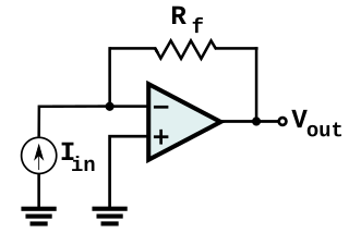
In electronics, a transimpedance amplifier (TIA) is a current to voltage converter, almost exclusively implemented with one or more operational amplifiers. The TIA can be used to amplify the current output of Geiger–Müller tubes, photo multiplier tubes, accelerometers, photo detectors and other types of sensors to a usable voltage. Current to voltage converters are used with sensors that have a current response that is more linear than the voltage response. This is the case with photodiodes where it is not uncommon for the current response to have better than 1% nonlinearity over a wide range of light input. The transimpedance amplifier presents a low impedance to the photodiode and isolates it from the output voltage of the operational amplifier. In its simplest form a transimpedance amplifier has just a large valued feedback resistor, Rf. The gain of the amplifier is set by this resistor and because the amplifier is in an inverting configuration, has a value of -Rf. There are several different configurations of transimpedance amplifiers, each suited to a particular application. The one factor they all have in common is the requirement to convert the low-level current of a sensor to a voltage. The gain, bandwidth, as well as current and voltage offsets change with different types of sensors, requiring different configurations of transimpedance amplifiers.
The operational amplifier integrator is an electronic integration circuit. Based on the operational amplifier (op-amp), it performs the mathematical operation of integration with respect to time; that is, its output voltage is proportional to the input voltage integrated over time.


