
An electronic oscillator is an electronic circuit that produces a periodic, oscillating electronic signal, often a sine wave or a square wave or a triangle wave. Oscillators convert direct current (DC) from a power supply to an alternating current (AC) signal. They are widely used in many electronic devices ranging from simplest clock generators to digital instruments and complex computers and peripherals etc. Common examples of signals generated by oscillators include signals broadcast by radio and television transmitters, clock signals that regulate computers and quartz clocks, and the sounds produced by electronic beepers and video games.

Oscillation is the repetitive variation, typically in time, of some measure about a central value or between two or more different states. The term vibration is precisely used to describe mechanical oscillation. Familiar examples of oscillation include a swinging pendulum and alternating current.

A phase-locked loop or phase lock loop (PLL) is a control system that generates an output signal whose phase is related to the phase of an input signal. There are several different types; the simplest is an electronic circuit consisting of a variable frequency oscillator and a phase detector in a feedback loop. The oscillator generates a periodic signal, and the phase detector compares the phase of that signal with the phase of the input periodic signal, adjusting the oscillator to keep the phases matched.
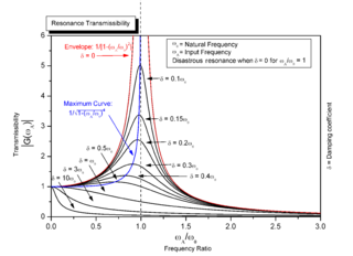
Resonance describes the phenomenon of increased amplitude that occurs when the frequency of a periodically applied force is equal or close to a natural frequency of the system on which it acts. When an oscillating force is applied at a resonant frequency of a dynamic system, the system will oscillate at a higher amplitude than when the same force is applied at other, non-resonant frequencies.

In electronics a relaxation oscillator is a nonlinear electronic oscillator circuit that produces a nonsinusoidal repetitive output signal, such as a triangle wave or square wave. The circuit consists of a feedback loop containing a switching device such as a transistor, comparator, relay, op amp, or a negative resistance device like a tunnel diode, that repetitively charges a capacitor or inductor through a resistance until it reaches a threshold level, then discharges it again. The period of the oscillator depends on the time constant of the capacitor or inductor circuit. The active device switches abruptly between charging and discharging modes, and thus produces a discontinuously changing repetitive waveform. This contrasts with the other type of electronic oscillator, the harmonic or linear oscillator, which uses an amplifier with feedback to excite resonant oscillations in a resonator, producing a sine wave. Relaxation oscillators are used to produce low frequency signals for applications such as blinking lights and electronic beepers and in voltage controlled oscillators (VCOs), inverters and switching power supplies, dual-slope analog to digital converters, and function generators.

A klystron is a specialized linear-beam vacuum tube, invented in 1937 by American electrical engineers Russell and Sigurd Varian, which is used as an amplifier for high radio frequencies, from UHF up into the microwave range. Low-power klystrons are used as oscillators in terrestrial microwave relay communications links, while high-power klystrons are used as output tubes in UHF television transmitters, satellite communication, radar transmitters, and to generate the drive power for modern particle accelerators.
The Hartley oscillator is an electronic oscillator circuit in which the oscillation frequency is determined by a tuned circuit consisting of capacitors and inductors, that is, an LC oscillator. The circuit was invented in 1915 by American engineer Ralph Hartley. The distinguishing feature of the Hartley oscillator is that the tuned circuit consists of a single capacitor in parallel with two inductors in series, and the feedback signal needed for oscillation is taken from the center connection of the two inductors.
A variable frequency oscillator (VFO) in electronics is an oscillator whose frequency can be tuned over some range. It is a necessary component in any tunable radio transmitter or receiver that works by the superheterodyne principle, and controls the frequency to which the apparatus is tuned.

A voltage-controlled oscillator (VCO) is an electronic oscillator whose oscillation frequency is controlled by a voltage input. The applied input voltage determines the instantaneous oscillation frequency. Consequently, a VCO can be used for frequency modulation (FM) or phase modulation (PM) by applying a modulating signal to the control input. A VCO is also an integral part of a phase-locked loop. VCOs are used in synthesizers to generate a waveform whose pitch can be adjusted by a voltage determined by a musical keyboard or other input.
Linear electronic oscillator circuits, which generate a sinusoidal output signal, are composed of an amplifier and a frequency selective element, a filter. A linear oscillator circuit which uses an RC network, a combination of resistors and capacitors, for its frequency selective part is called an RC oscillator.
In electronics, a frequency multiplier is an electronic circuit that generates an output signal and that output frequency is a harmonic (multiple) of its input frequency. Frequency multipliers consist of a nonlinear circuit that distorts the input signal and consequently generates harmonics of the input signal. A subsequent bandpass filter selects the desired harmonic frequency and removes the unwanted fundamental and other harmonics from the output.

A Wien bridge oscillator is a type of electronic oscillator that generates sine waves. It can generate a large range of frequencies. The oscillator is based on a bridge circuit originally developed by Max Wien in 1891 for the measurement of impedances. The bridge comprises four resistors and two capacitors. The oscillator can also be viewed as a positive gain amplifier combined with a bandpass filter that provides positive feedback. Automatic gain control, intentional non-linearity and incidental non-linearity limit the output amplitude in various implementations of the oscillator.

A ring oscillator is a device composed of an odd number of NOT gates in a ring, whose output oscillates between two voltage levels, representing true and false. The NOT gates, or inverters, are attached in a chain and the output of the last inverter is fed back into the first.

An optical parametric oscillator (OPO) is a parametric oscillator that oscillates at optical frequencies. It converts an input laser wave with frequency into two output waves of lower frequency by means of second-order nonlinear optical interaction. The sum of the output waves' frequencies is equal to the input wave frequency: . For historical reasons, the two output waves are called "signal" and "idler", where the output wave with higher frequency is the "signal". A special case is the degenerate OPO, when the output frequency is one-half the pump frequency, , which can result in half-harmonic generation when signal and idler have the same polarization.

A backward wave oscillator (BWO), also called carcinotron or backward wave tube, is a vacuum tube that is used to generate microwaves up to the terahertz range. Belonging to the traveling-wave tube family, it is an oscillator with a wide electronic tuning range.

A parametric oscillator is a driven harmonic oscillator in which the oscillations are driven by varying some parameter of the system at some frequency, typically different from the natural frequency of the oscillator. A simple example of a parametric oscillator is a child pumping a playground swing by periodically standing and squatting to increase the size of the swing's oscillations. The child's motions vary the moment of inertia of the swing as a pendulum. The "pump" motions of the child must be at twice the frequency of the swing's oscillations. Examples of parameters that may be varied are the oscillator's resonance frequency and damping .
A frequency synthesizer is an electronic circuit that generates a range of frequencies from a single reference frequency. Frequency synthesizers are used in many modern devices such as radio receivers, televisions, mobile telephones, radiotelephones, walkie-talkies, CB radios, cable television converter boxes, satellite receivers, and GPS systems. A frequency synthesizer may use the techniques of frequency multiplication, frequency division, direct digital synthesis, frequency mixing, and phase-locked loops to generate its frequencies. The stability and accuracy of the frequency synthesizer's output are related to the stability and accuracy of its reference frequency input. Consequently, synthesizers use stable and accurate reference frequencies, such as those provided by a crystal oscillator.
Injection locking and injection pulling are the frequency effects that can occur when a harmonic oscillator is disturbed by a second oscillator operating at a nearby frequency. When the coupling is strong enough and the frequencies near enough, the second oscillator can capture the first oscillator, causing it to have essentially identical frequency as the second. This is injection locking. When the second oscillator merely disturbs the first but does not capture it, the effect is called injection pulling. Injection locking and pulling effects are observed in numerous types of physical systems, however the terms are most often associated with electronic oscillators or laser resonators.
Optical heterodyne detection is a method of extracting information encoded as modulation of the phase, frequency or both of electromagnetic radiation in the wavelength band of visible or infrared light. The light signal is compared with standard or reference light from a "local oscillator" (LO) that would have a fixed offset in frequency and phase from the signal if the latter carried null information. "Heterodyne" signifies more than one frequency, in contrast to the single frequency employed in homodyne detection.
The concept of a linewidth is borrowed from laser spectroscopy. The linewidth of a laser is a measure of its phase noise. The spectrogram of a laser is produced by passing its light through a prism. The spectrogram of the output of a pure noise-free laser will consist of a single infinitely thin line. If the laser exhibits phase noise, the line will have non-zero width. The greater the phase noise, the wider the line. The same will be true with oscillators. The spectrum of the output of a noise-free oscillator has energy at each of the harmonics of the output signal, but the bandwidth of each harmonic will be zero. If the oscillator exhibits phase noise, the harmonics will not have zero bandwidth. The more phase noise the oscillator exhibits, the wider the bandwidth of each harmonic.