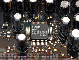
In electronics, an analog-to-digital converter is a system that converts an analog signal, such as a sound picked up by a microphone or light entering a digital camera, into a digital signal. An ADC may also provide an isolated measurement such as an electronic device that converts an analog input voltage or current to a digital number representing the magnitude of the voltage or current. Typically the digital output is a two's complement binary number that is proportional to the input, but there are other possibilities.

In telecommunications and signal processing, companding is a method of mitigating the detrimental effects of a channel with limited dynamic range. The name is a portmanteau of the words compressing and expanding, which are the functions of a compander at the transmitting and receiving ends, respectively. The use of companding allows signals with a large dynamic range to be transmitted over facilities that have a smaller dynamic range capability. Companding is employed in telephony and other audio applications such as professional wireless microphones and analog recording.
In signal processing, distortion is the alteration of the original shape of a signal. In communications and electronics it means the alteration of the waveform of an information-bearing signal, such as an audio signal representing sound or a video signal representing images, in an electronic device or communication channel.

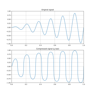
The μ-law algorithm is a companding algorithm, primarily used in 8-bit PCM digital telecommunications systems in North America and Japan. It is one of the two companding algorithms in the G.711 standard from ITU-T, the other being the similar A-law. A-law is used in regions where digital telecommunication signals are carried on E-1 circuits, e.g. Europe.
Noise figure (NF) and noise factor (F) are figures of merit that indicate degradation of the signal-to-noise ratio (SNR) that is caused by components in a signal chain. These figures of merit are used to evaluate the performance of an amplifier or a radio receiver, with lower values indicating better performance.

Signal-to-noise ratio is a measure used in science and engineering that compares the level of a desired signal to the level of background noise. SNR is defined as the ratio of signal power to noise power, often expressed in decibels. A ratio higher than 1:1 indicates more signal than noise.
The total harmonic distortion is a measurement of the harmonic distortion present in a signal and is defined as the ratio of the sum of the powers of all harmonic components to the power of the fundamental frequency. Distortion factor, a closely related term, is sometimes used as a synonym.

In electronics, a digital-to-analog converter is a system that converts a digital signal into an analog signal. An analog-to-digital converter (ADC) performs the reverse function.
A low-noise amplifier (LNA) is an electronic component that amplifies a very low-power signal without significantly degrading its signal-to-noise ratio (SNR). Any electronic amplifier will increase the power of both the signal and the noise present at its input, but the amplifier will also introduce some additional noise. LNAs are designed to minimize that additional noise, by choosing special components, operating points, and circuit topologies. Minimizing additional noise must balance with other design goals such as power gain and impedance matching.

A preamplifier, also known as a preamp, is an electronic amplifier that converts a weak electrical signal into an output signal strong enough to be noise-tolerant and strong enough for further processing, or for sending to a power amplifier and a loudspeaker. Without this, the final signal would be noisy or distorted. They are typically used to amplify signals from analog sensors such as microphones and pickups. Because of this, the preamplifier is often placed close to the sensor to reduce the effects of noise and interference.
The sensitivity of an electronic device, such as a communications system receiver, or detection device, such as a PIN diode, is the minimum magnitude of input signal required to produce a specified output signal having a specified signal-to-noise ratio, or other specified criteria. In general, it is the signal level required for a particular quality of received information.
In signal processing, oversampling is the process of sampling a signal at a sampling frequency significantly higher than the Nyquist rate. Theoretically, a bandwidth-limited signal can be perfectly reconstructed if sampled at the Nyquist rate or above it. The Nyquist rate is defined as twice the bandwidth of the signal. Oversampling is capable of improving resolution and signal-to-noise ratio, and can be helpful in avoiding aliasing and phase distortion by relaxing anti-aliasing filter performance requirements.
In telecommunications, the carrier-to-noise ratio, often written CNR or C/N, is the signal-to-noise ratio (SNR) of a modulated signal. The term is used to distinguish the CNR of the radio frequency passband signal from the SNR of an analog base band message signal after demodulation. For example, with FM radio, the strength of the 100 MHz carrier with modulations would be considered for CNR, whereas the audio frequency analogue message signal would be for SNR; in each case, compared to the apparent noise. If this distinction is not necessary, the term SNR is often used instead of CNR, with the same definition.

In digital audio using pulse-code modulation (PCM), bit depth is the number of bits of information in each sample, and it directly corresponds to the resolution of each sample. Examples of bit depth include Compact Disc Digital Audio, which uses 16 bits per sample, and DVD-Audio and Blu-ray Disc, which can support up to 24 bits per sample.
Effective number of bits (ENOB) is a measure of the dynamic range of an analog-to-digital converter (ADC), digital-to-analog converter, or their associated circuitry. The resolution of an ADC is specified by the number of bits used to represent the analog value. Ideally, a 12-bit ADC will have an effective number of bits of almost 12. However, real signals have noise, and real circuits are imperfect and introduce additional noise and distortion. Those imperfections reduce the number of bits of accuracy in the ADC. The ENOB describes the effective resolution of the system in bits. An ADC may have a 12-bit resolution, but the effective number of bits, when used in a system, may be 9.5.
In array antenna systems, array gain is the measure of the improvement in signal-to-noise ratio (SNR) achieved by the array. It is calculated as the SNR of the array output signal divided by the SNR of the array input signal. Intuitively, the array gain is realized by the fact that the signal is coherently added from N array elements, while the noise is incoherently added from those same elements. If the noise is presumed to be uncorrelated the array gain is ≤ N, the number of array elements, and the array gain reduces to the inverse of the square of the 2-norm of the array weight vector, under the assumption that the weight vector is normalized such that its sum is unity, so that
The signal-to-interference ratio, also known as the carrier-to-interference ratio, is the quotient between the average received modulated carrier power S or C and the average received co-channel interference power I, i.e. crosstalk, from other transmitters than the useful signal.
Spurious-free dynamic range (SFDR) is the strength ratio of the fundamental signal to the strongest spurious signal in the output. It is also defined as a measure used to specify analog-to-digital and digital-to-analog converters and radio receivers.
Signal-to-noise and distortion ratio (SINADR) is a measurement of the purity of a signal. SINADR is typically used in data converter specifications. SINADR is defined as:
Time interleaved (TI) ADCs are Analog-to-Digital Converters (ADCs) that involve M converters working in parallel. Each of the M converters is referred to as sub-ADC, channel or slice in the literature. The time interleaving technique, akin to multithreading in computing, involves using multiple converters in parallel to sample the input signal at staggered intervals, increasing the overall sampling rate and improving performance without overburdening the single ADCs.


