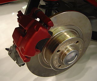
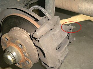
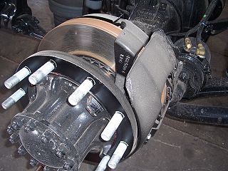
A disc brake is a type of brake that uses the calipers to squeeze pairs of pads against a disc or a "rotor" to create friction. This action slows the rotation of a shaft, such as a vehicle axle, either to reduce its rotational speed or to hold it stationary. The energy of motion is converted into waste heat which must be dispersed.
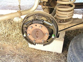
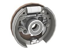
A drum brake is a brake that uses friction caused by a set of shoes or pads that press outward against a rotating cylinder-shaped part called a brake drum.
A brake is a mechanical device that inhibits motion by absorbing energy from a moving system. It is used for slowing or stopping a moving vehicle, wheel, axle, or to prevent its motion, most often accomplished by means of friction.
A bicycle brake reduces the speed of a bicycle or prevents it from moving. The three main types are: rim brakes, disc brakes, and drum brakes.

The vacuum brake is a braking system employed on trains and introduced in the mid-1860s. A variant, the automatic vacuum brake system, became almost universal in British train equipment and in countries influenced by British practice. Vacuum brakes also enjoyed a brief period of adoption in the United States, primarily on narrow-gauge railroads. Their limitations caused them to be progressively superseded by compressed air systems starting in the United Kingdom from the 1970s onward. The vacuum brake system is now obsolete; it is not in large-scale usage anywhere in the world, other than in South Africa, largely supplanted by air brakes.

In mechanical or automotive engineering, a freewheel or overrunning clutch is a device in a transmission that disengages the driveshaft from the driven shaft when the driven shaft rotates faster than the driveshaft. An overdrive is sometimes mistakenly called a freewheel, but is otherwise unrelated.
Engine braking occurs when the retarding forces within an engine are used to slow down a motor vehicle, as opposed to using additional external braking mechanisms such as friction brakes or magnetic brakes.
Vehicle braking system fade, or brake fade, is the reduction in stopping power that can occur after repeated or sustained application of the brakes, especially in high load or high speed conditions. Brake fade can be a factor in any vehicle that utilizes a friction braking system including automobiles, trucks, motorcycles, airplanes, and bicycles.

In automotive engineering, the master cylinder is a control device that converts force into hydraulic pressure. This device controls slave cylinders located at the other end of the hydraulic brake system.
Brake bleeding is the procedure performed on hydraulic brake systems whereby the brake lines are purged of any air bubbles. This is necessary because, while the brake fluid is an incompressible liquid, air bubbles are compressible gas and their presence in the brake system greatly reduces the hydraulic pressure that can be developed within the system. The same methods used for bleeding are also used for brake flushing or purging, where the old fluid is replaced with new fluid, which is necessary maintenance.

A hydraulic brake is an arrangement of braking mechanism which uses brake fluid, typically containing glycol ethers or diethylene glycol, to transfer pressure from the controlling mechanism to the braking mechanism.

In road vehicles, the parking brake, also known as a handbrake or emergency brake (e-brake), is a mechanism used to keep the vehicle securely motionless when parked. Parking brakes often consist of a pulling mechanism attached to a cable which is connected to two wheel brakes. In most vehicles, the parking brake operates only on the rear wheels, which have reduced traction while braking. The mechanism may be a hand-operated lever, a straight pull handle located near the steering column or a foot-operated pedal located with the other pedals.

A retarder is a device used to augment or replace some of the functions of primary friction-based braking systems, usually on heavy vehicles. Retarders serve to slow vehicles, or maintain a steady speed while traveling down a hill, and help prevent the vehicle from "running away" by accelerating down the hill. They are not usually capable of bringing vehicles to a standstill, as their effectiveness diminishes as vehicle speed lowers. They are usually used as an additional "assistance" to slow vehicles, with the final braking done by a conventional friction braking system. As the friction brake will be used less, particularly at higher speeds, their service life is increased, and since in those vehicles the brakes are air-actuated helps to conserve air pressure too.
Brake pads are a component of disc brakes used in automotive and other applications. Brake pads are composed of steel backing plates with friction material bound to the surface that faces the disc brake rotors.
An air brake or, more formally, a compressed-air-brake system, is a type of friction brake for vehicles in which compressed air pressing on a piston is used to apply the pressure to the brake pad or brake shoe needed to stop the vehicle. Air brakes are used in large heavy vehicles, particularly those having multiple trailers which must be linked into the brake system, such as trucks, buses, trailers, and semi-trailers, in addition to their use in railroad trains. George Westinghouse first developed air brakes for use in railway service. He patented a safer air brake on March 5, 1872. Westinghouse made numerous alterations to improve his air pressured brake invention, which led to various forms of the automatic brake. In the early 20th century, after its advantages were proven in railway use, it was adopted by manufacturers of trucks and heavy road vehicles.
In the automotive industry, brake-by-wire technology is the ability to control brakes through electrical means. It can be designed to supplement ordinary service brakes or it can be a standalone brake system.
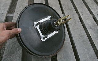
A vacuum servo is a component used on motor vehicles in their braking system, to provide assistance to the driver by decreasing the braking effort. In the US it is commonly called a brake booster.
A Brake wear indicator is used to warn the user and/or owner of a vehicle that the brake pad is in need of replacement. The main area of use for this is on motor vehicles with more than three wheels. However brake wear indicators are also useful for brake pads in industrial applications, including wind turbines and cranes.
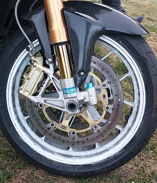
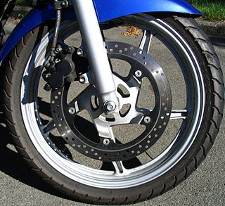
Motorcycle braking systems have varied throughout time, as motorcycles evolved from bicycles with an engine attached, to the 220 mph (350 km/h) prototype motorcycles seen racing in MotoGP. Most systems work by converting kinetic energy into thermal energy (heat) by friction. On motorcycles, approximately 70% of the braking effort is performed by the front brake. This however can vary for individual motorcycles; longer-wheelbase types having more weight biased rearward, such as cruisers and tourers, can have a`greater effort applied by the rear brake. In contrast, sports bikes with a shorter wheelbase and more vertical fork geometry can tolerate higher front braking loads. For these reasons, motorcycles tend to have a vastly more powerful front brake compared to the rear.