Rail fastening system

Last updated
Elements of a baseplate-based rail fastening system
Screw for fixing plate to sleeper
Elastomeric pad supporting rail
Tension washer
Rail clamp
Tensioning bolt (nut not shown)
Baseplate Drobne kolejivo.JPG
Elements of a baseplate-based rail fastening system
  1. Screw for fixing plate to sleeper
  2. Elastomeric pad supporting rail
  3. Tension washer
  4. Rail clamp
  5. Tensioning bolt (nut not shown)
  6. Baseplate
Unimog pushing a "Spindle Precision Wrenching Unit" used for automatic and synchronous tightening and loosening of rail fastenings Total reconstruction of Neunkirchen station (254).jpg
Unimog pushing a "Spindle Precision Wrenching Unit" used for automatic and synchronous tightening and loosening of rail fastenings
Mabbett Railway Chair Manufacturing Company share certificate (1867) Mabbett Railway Chair Manufacturing Company - share certificate - 1867.jpg
Mabbett Railway Chair Manufacturing Company share certificate (1867)

A rail fastening system is a means of fixing rails to railroad ties (North America) or sleepers (British Isles, Australasia, and Africa). The terms rail anchors, tie plates, chairs and track fasteners are used to refer to parts or all of a rail fastening system. The components of a rail fastening system may also be known collectively as other track material, or OTM for short. Various types of fastening have been used over the years.

Contents

History and overview

The earliest wooden rails were fixed to wooden sleepers by pegs through holes in the rail, or by nails. By the 18th century, cast iron rails had come into use, and also had holes in the rail itself to allow them to be fixed to a support. [1] 18th century developments such as the flanged rail and fish bellied rail also had holes in the rail itself; when stone block sleepers were used the nails were driven into a wooden block which had been inserted into a recess in the block. The first chair for a rail is thought to have been introduced in 1797 which attached to the rail on the vertical web via bolts. [2]

Assembled example Rail fastening 01 ies.jpg
Assembled example

By the 1820s the first shaped rolled rails had begun to be produced initially of a T shape which required a chair to hold them; the rails were held in position by iron wedges (which sometimes caused the rail to break when forced in) and later by wooden wedges, which became the standard. [3] In the 1830s Robert L. Stevens invented the flanged 'tee' rail (actually a distorted I beam), which had a flat bottom and required no chair; a similar design was the contemporary bridge rail (of inverted U section with a bottom flange and laid on longitudinal sleepers); these rails were initially nailed directly to the sleeper. [4]

In North American practice the flanged T rail became the standard, later being used with tie-plates. Elsewhere T rails were replaced by bull head rails of a rounded 'I' or 'figure-8' appearance which still required a supporting chair. Eventually the flanged T rail became commonplace on all the world's railways, though differences in the fixing system still exist.

Symbolism and significance

A golden tie, also known as a golden spike or the last spike, may be used to symbolize the start or the completion of an endeavor. These are less often silver or another precious material.

Historically, a ceremonial Golden Spike driven by Leland Stanford connected the rails of the First Transcontinental Railroad across the United States. The valuable rail fastening spike represented the merge of the Central Pacific and Union Pacific railroads on May 10, 1869, at Promontory Summit, Utah Territory. The rail spike has entered American popular consciousness in this manner; the driving of the Golden Spike was a key point in the development of the western seaboard in North America and was recognized as a national achievement and demonstration of progress. Since, railroad workers have been celebrated in popular culture, including in song and verse. [5]

Most recently, a Golden Spike marked the completion of the longest transportation tunnel in the world, the Gotthard Base Tunnel, which opened 1 June 2016. Full rail service began on 11 December 2016. Its functional length is 57.09 km (35.5 mi) and it is the world's deepest traffic tunnel.

Spikes and screws

Rail spikes

Rusted cut spikes (scale in inches) Railroad spikes.JPG
Rusted cut spikes (scale in inches)
Dog spike Spike 001.jpg
Dog spike

A rail spike (also known as a cut spike or crampon) is a large nail with an offset head that is used to secure rails and base plates to railroad ties (sleepers) in the track. Robert Livingston Stevens is credited with the invention of the rail spike, [6] the first recorded use of which was in 1832. [7] The railroad spike was an invention which resulted from the state of industrialisation in the United States in the early 19th century: English mainline railways of that period used heavy and expensive cast iron chairs to secure T-shaped rails; instead, Stevens added a supporting base to the T rail which could be fixed with a simple spike. [8] [9] In 1982, the spike was still the most common rail fastening in North America. Common sizes are from 916 to 1016 inch (14 to 16 mm) square and 5+12 to 6 inches (140 to 150 mm) long. [10] :582–3

Railroad spikes of the old Jezreel Valley railway (part of the Hejaz Railway), found near Kfar Baruch (Israel) HejazSpike.jpg
Railroad spikes of the old Jezreel Valley railway (part of the Hejaz Railway), found near Kfar Baruch (Israel)

A rail spike is roughly chisel-shaped and with a flat edged point; the spike is driven with the edge perpendicular to the grain, which gives greater resistance to loosening. [11] The main function is to keep the rail in gauge. When attaching tie plates the attachment is made as strong as possible, whereas when attaching a rail to tie or tie plate the spike is not normally required to provide a strong vertical force, allowing the rail some freedom of movement. [10] :455,581–2

On smaller scale jobs, spikes are still driven into wooden sleepers by hammering them with a spike maul, though this manual work has been largely replaced by hydraulic tools [12] and machines, commonly called "spikers" (a machine that removes spikes is called a "spike puller"). [13] Splitting of the wood can be limited by pre-boring spike holes or adding steel bands around the wood. [10] :455

For use in the United States three basic standards are described in the ASTM A65 standard, for different carbon steel contents. [14]

A dog spike is functionally equivalent to a cut spike and is also square in horizontal section and of similar dimensions, but has a pointed penetrating end, and the rail (or "plate holding") head has two lugs on either side, giving the impression of a dog's head and aiding spike removal. [15]

Chair screws

Rusted chair screw Rail bolt-93489.jpg
Rusted chair screw
Chair screw (French: Tire-fonds) Rusty Railroad Spikes 3008px.jpg
Chair screw (French: Tire-fonds)

A chair screw (also known as coach screw [16] ) is a large (~6 in or 152 mm length, slightly under 1 in or 25 mm diameter) metal screw used to fix a chair (for bullhead rail), baseplate (for flat bottom rail) or to directly fasten a rail. Chair screws are screwed into a hole bored in the sleeper. [17] The chair screw has a higher cost to manufacture than the rail spike, but has the advantage of greater fixing powerapproximately twice that of a rail spike [18] and can be used in combination with spring washers. [17]

The chair screw was first introduced in 1860 in France (French tire-fond ) and became common in continental Europe. [19]

A dog screw is a tradename variant of the screw spike. [20]

Fang bolts

Fang bolts or rail anchor bolts have also been used for fixing rails or chairs to sleepers. The fang bolt is a bolt inserted through a hole in the sleeper with a fanged nut that bites into the lower surface of the sleeper. For fastening flat-bottomed rails, an upper-lipped washer can be used to grip the edge of the rail. They are more resistant to loosening by vibrations and movement of the rail. [21] They are thought more effective than spikes and screws and so are used in positions such as switch (point) tieplates [22] and on sharp curves. [23]

Spring spikes

Spring spike fastener (German: Oberbau Hf ) Spring spike rail fastener, without baseplate, cropped version.JPG
Spring spike fastener (German: Oberbau Hf )

Spring spikes or elastic rail spikes [25] are used with flat-bottomed rail, baseplates and wooden sleepers. The spring spike holds the rail down and prevents tipping and also secures the baseplate to the sleeper. [26] The Macbeth spike (trade name) is a two-pronged U-shaped staple-like spike bent so that it appears M-shaped when viewed from the side. [27] [28] Inverted J-shaped single pointed spikes have also been used. [29]

Fixing equipment

The spike maul, also known as a spiking hammer, is a type of sledgehammer with a long thin head which was originally used to drive spikes. [30] [31]

Manual hole drilling and spike or screw insertion and removal have been replaced by semi-automated or automated machines, which are driven electrically, by pneumatics, by hydraulics, or are powered by a two-stroke engine. Machines that remove spikes are called spike pullers. [32] [33] [34]

Rail supports

Chairs

Cross section of early T rail, chair and key Diagram of section of Leeds and Selby Railway Chair showing rail and key.JPG
Cross section of early T rail, chair and key

The earliest rail chairs, made of cast iron and introduced around 1800, were used to fix and support cast-iron rails at their ends; [2] they were also used to join adjacent rails. [35]

In the 1830s rolled T-shaped (or single-flanged T parallel rail) and I-shaped (or double-flanged T parallel or bullhead) rails were introduced; both required cast-iron chairs to support them. [36] Originally, iron keys were used to wedge the rail into the vertical parallel jaws of the chair; these were superseded by entirely wooden keys. [36] The wooden keys were formed from oak, steam softened and then compressed with hydraulic presses and stored in a drying house. When inserted into the chair, exposure to the wet atmosphere caused the key to expand, firmly holding the rail. [37] The wedge may be on the inside or outside of the rail. In Britain they were usually on the outside. [38]

Chairs have been fixed to the sleeper using wooden spikes (trenails), screws, fang-bolts or spikes. [39]

In most of the world, flat-bottomed rail and baseplates became the standard. However, in Britain, bullhead rail-and-chairs remained in use until the middle of the twentieth century. [26]

Tie plates

A tie plate, baseplate or sole plate is a steel plate for centering and reinforcing the attachment point on the rail tracks between a flanged T rail and a railroad tie. The tie plate increases bearing area and holds the rail to correct gauge. It is fastened to wooden ties by means of spikes or bolts through holes in the plate.

The part of the plate under the rail base is tapered, setting the inboard cant of the rail, typically "one in forty" (or 1.4 degrees ). The top surface of the plate has one or two shoulders that fit against the edges of the base of the rail. The double-shoulder type is currently used. Older single-shoulder types were adaptable for various rail widths, with the single shoulder positioned on the outside (field side) of the rails. Most plates are slightly wider on the field side, without which the plates tend to cut more into the outsides of the tie, reducing cant angle.

Many railways use large wood screws, also called lag screws, to fasten the tie plates (or baseplates) to the railroad ties.

Tie plates came into use around the year 1900, before which time flanged T rail was spiked directly to the ties.

Clips

A variety of different types of heavy-duty clips are used to fasten the rails to the underlying baseplate, one common one being the Pandrol fastener (Pandrol clip), named after its maker, which is shaped like a stubby paperclip. [40] Another one is the Vossloh Tension Clamp. [41] Clips are an alternative to spikes.

The newer Pandrol fastclip is applied at right angles to the rail. Because the clip is captive, it has to be installed at the time of manufacture of the concrete sleeper.

Rail anchors

Rail anchors, also called anticreepers, are spring steel clips that attach to the underside of the rail baseplate and bear against the sides of the sleepers to prevent longitudinal movement of the rail, either from changes in temperature or through vibration. Anchors may be attached and removed either by hand with hammers, or by an anchor machine.

See also

Related Research Articles

A flange is a protruded ridge, lip or rim, either external or internal, that serves to increase strength ; for easy attachment/transfer of contact force with another object ; or for stabilizing and guiding the movements of a machine or its parts. Flanges are often attached using bolts in the pattern of a bolt circle.

<span class="mw-page-title-main">Wagonway</span> Railway using horses to pull goods wagons

Wagonways, also known as horse-drawn railways and horse-drawn railroad consisted of the horses, equipment and tracks used for hauling wagons, which preceded steam-powered railways. The terms plateway, tramway, dramway, were used. The advantage of wagonways was that far bigger loads could be transported with the same power.
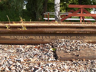
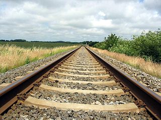
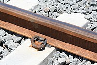
<span class="mw-page-title-main">Railway track</span> Rail infrastructure

A railway track or railroad track, also known as a train track or permanent way, is the structure on a railway or railroad consisting of the rails, fasteners, railroad ties and ballast, plus the underlying subgrade. It enables trains to move by providing a dependable surface for their wheels to roll upon. Early tracks were constructed with wooden or cast iron rails, and wooden or stone sleepers; since the 1870s, rails have almost universally been made from steel.

<span class="mw-page-title-main">HO scale</span> Model railroad scale of 1:87

HO or H0 is a rail transport modelling scale using a 1:87 scale. It is the most popular scale of model railway in the world. The rails are spaced 16.5 millimetres (0.650 in) apart for modelling 1,435 mm standard gauge tracks and trains in HO.

<span class="mw-page-title-main">History of the railway track</span>

The railway track or permanent way is the elements of railway lines: generally the pairs of rails typically laid on the sleepers or ties embedded in ballast, intended to carry the ordinary trains of a railway. It is described as a permanent way because, in the earlier days of railway construction, contractors often laid a temporary track to transport spoil and materials about the site; when this work was substantially completed, the temporary track was taken up and the permanent way installed.

<span class="mw-page-title-main">Railroad tie</span> Support for the rails in railroad tracks

A railroad tie, crosstie, railway tie or railway sleeper is a rectangular support for the rails in railroad tracks. Usually laid perpendicular to the rails, ties transfer loads to the track ballast and subgrade, hold the rails upright and keep them spaced to the correct gauge.

Rail transport terms are a form of technical terminology applied to railways. Although many terms are uniform across different nations and companies, they are by no means universal, with differences often originating from parallel development of rail transport systems in different parts of the world, and in the national origins of the engineers and managers who built the inaugural rail infrastructure. An example is the term railroad, used in North America, and railway, generally used in English-speaking countries outside North America and by the International Union of Railways. In English-speaking countries outside the United Kingdom, a mixture of US and UK terms may exist.

<span class="mw-page-title-main">Maintenance of way</span> Aspect of rail transport operations

Maintenance of way refers to the maintenance, construction, and improvement of rail infrastructure, including tracks, ballast, grade, and lineside infrastructure such as signals and signs.

<span class="mw-page-title-main">Treenail</span> Wooden fastener

A treenail, also trenail, trennel, or trunnel, is a wooden peg, pin, or dowel used to fasten pieces of wood together, especially in timber frames, covered bridges, wooden shipbuilding and boat building. It is driven into a hole bored through two pieces of structural wood.

<span class="mw-page-title-main">Little Eaton Gangway</span> British narrow gauge industrial wagonway (1795-1908)

The Little Eaton Gangway, officially the Derby Canal Railway, was a narrow gauge industrial wagonway serving the Derby Canal, in England, at Little Eaton in Derbyshire.

<span class="mw-page-title-main">Fishplate</span> Metal part used to join two rails together

A fishplate, splice bar or joint bar is a metal connecting plate used to bolt the ends of two rails into a continuous track. The name is derived from fish, a wooden reinforcement of a "built-up" ship's mast that helped round out its desired profile. The top and bottom faces taper inwards along their short dimensions to create an even alignment between the two rails when the fish plate is wedged into place by tightening its bolts during installation.

<span class="mw-page-title-main">Plateway</span> Early kind of flanged cast-iron railway

A plateway is an early kind of railway, tramway or wagonway, where the rails are made from cast iron. They were mainly used for about 50 years up to 1830, though some continued later.
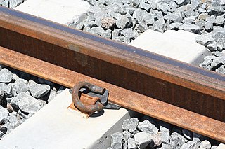
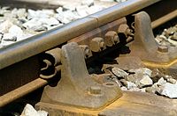
<span class="mw-page-title-main">Pandrol</span> Rail fastener manufacturer

Pandrol is a global rail technology company, founded in 1953 and operating in over 100 countries worldwide, with over 400 railway systems having adopted its products.

<span class="mw-page-title-main">Howe truss</span>

A Howe truss is a truss bridge consisting of chords, verticals, and diagonals whose vertical members are in tension and whose diagonal members are in compression. The Howe truss was invented by William Howe in 1840, and was widely used as a bridge in the mid to late 1800s.

<span class="mw-page-title-main">Rail profile</span> Cross sectional shape of a railway rail

The rail profile is the cross sectional shape of a railway rail, perpendicular to its length.

<span class="mw-page-title-main">Concrete sleeper</span> Railway sleeper made out of prestressed concrete

A concrete sleeper or concrete tie is a type of railway sleeper or railroad tie made out of steel reinforced concrete.

<span class="mw-page-title-main">Screw</span> Type of fastener characterized by a thread wrapped around a cylinder core

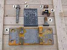
A screw is an externally helical threaded fastener capable of being tightened or released by a twisting force (torque) to the head. The most common uses of screws are to hold objects together and there are many forms for a variety of materials. Screws might be inserted into holes in assembled parts or a screw may form its own thread.

<span class="mw-page-title-main">Baulk road</span> Railway track on undergirding timber bearings

Baulk road is the name given to a type of railway track or 'rail road' that is formed using rails carried on continuous timber bearings, as opposed to the more familiar 'cross-sleeper' track that uses closely spaced sleepers or ties to give intermittent support to stronger rails.

A stoneblower is a railway track maintenance machine that automatically lifts and packs the sleepers with small grade ballast, which is blown under the sleepers to level the track. An alternative to the use of a ballast tamper, the totally self-contained machine levels track without the use of a large gang of workmen.

The Spalding railway was a German narrow gauge railway system invented, patented and developed by Heinrich Andreas Spalding in 1884 for forestry and agriculture applications. It was similar to the Decauville railway, which had been invented and patented in France eight years earlier.

References

  1. Raidabaugh (1915), p. 5-7.
  2. 1 2 Origin and Development of the Railway Rail, G. P. Raidabaugh, pp.8-9
  3. Origin and Development of the Railway Rail, G. P. Raidabaugh, pp.14-19
  4. Origin and Development of the Railway Rail, G. P. Raidabaugh, pp.19-24
  5. Norm Cohen; David Cohen (2000). Long steel rail: the railroad in American folksong. University of Illinois Press. ISBN   9780252068812.
  6. "October 18 - Today in Science History". www.todayinsci.com. Robert Livingston Stevens.
  7. George Iles (1912). Leading American inventors. H. Holt and company, New York. p. 23.
  8. Raidabaugh (1915), p. 20.
  9. "The Rail Spike and The Locomotive". chestofbooks.com. Scientific American.
  10. 1 2 3 Hay, William Walter (1953). Railroad Engineering, Volume 1. John Wiley & Sons.
  11. "railroad spikes". www.sizes.com.
  12. "Spike Drivers | Stanley Hydraulic". www.stanleyhydraulics.com. Retrieved 2016-12-23.
  13. Solomon (2001), p. 61-64.
  14. "ASTM A65 - 07". www.astm.org. ASTM International (American Society for Testing and Materials).
  15. Mundrey (2000), p. 130–131.
  16. "Hay J.G., B.Sc, A.M.I.C.E., M.I.Struct.E. - Railway Sleepers and Fastenings on the South African Railways - Civil Engineer in South Africa, June 1962, p105", www.journals.co.za
  17. 1 2 Railroad engineering, Volume 1, William Walter Hay, pp.585
  18. Orrock (1918), p. 188-204.
  19. Sellew (1915), p. 161-163.
  20. "AJAX - Dog Screw Railway Fasteners for Rail Tracks With Timber Sleepers", www.railway-technology.com
  21. Railway Appliances, John Wolfe Barry, pp.53-54,73
  22. Mundrey (2000), p. 156–157.
  23. William Hemingway Mills (1898). Railway Construction. Longmans, Green, and Co. pp. 224, also fig.331–334 (p.221).
  24. Wolfgang Schiemann (2002). Schienenverkehrstechnik: Grundlagen der Gleistrassierung. Teubner B.G. p. 283. ISBN   3519003635.
  25. Bonnett (2005), p. 65, 5.10 Rail Fastenings, Baseplates and Pads
  26. 1 2 Craig (2015).
  27. National Research Council (U.S.). Railroad Research Information Service; United States. Federal Railroad Administration (1973). Special bibliography: safety-related technology. National Academies. 032978 Spring Steel Rail Spikes (from Railway Gazette, Feb. 1948, Vol.88, pp.191-2).
  28. Ellis (2006), p. 211, Macbeth Spike.
  29. Ellis (2006), p. 114, Elastic Spike.
  30. Sellew (1915), p. 215-216.
  31. Ron Fitch (2006). Australian Railwayman: From Cadet Engineer to Railways Commissioner. Rosenberg Publishing. p. 220.
  32. Solomon (2001), p. 59–62.
  33. "Workin' on the Railroad". Popular Mechanics. Hearst Magazines. 84 (4): 20–27. October 1945. ISSN   0032-4558.
  34. "Mechanised section gang now lays railroad ties". Popular Science. Bonnier Corporation. 168 (2): 168–9. February 1956. ISSN   0161-7370.
  35. Raidabaugh (1915), p. 11-12.
  36. 1 2 Clark (1855), p. 280.
  37. Williams, Frederick Smeaton (1852). Our Iron Roads: Their History, Construction and Influences: With numerous illustrations. Ingram. pp. 199–200.
  38. Railway Appliances, John Wolfe Barry, pp.43-51
  39. Railway Appliances, John Wolfe Barry, pp.71
  40. "Pandrol - Pandrol - The future of rail fastenings". www.pandrol.com.
  41. "vossloh-fastening-systems.com - Home". www.vosslo-fastening-systems.de.

Bibliography

Further reading