Baulk road

Last updated

A baulk road crossing showing the baulks (under the rails) and transoms (to maintain the gauge) Baulk road crossing.jpg
A baulk road crossing showing the baulks (under the rails) and transoms (to maintain the gauge)

Baulk road is the name given to a type of railway track or 'rail road' that is formed using rails carried on continuous timber bearings, as opposed to the more familiar 'cross-sleeper' track that uses closely spaced sleepers or ties to give intermittent support to stronger rails.

Contents

Baulk road was popularised by Isambard Kingdom Brunel for his 7 ft 14 in (2,140 mm) broad gauge railways in the UK, but has also been used for other railways and can still be found in modified form in special locations on present day railways.

Development

A section through a baulk with bridge rail on top Baulk road section through longitudinal.jpg
A section through a baulk with bridge rail on top

Brunel sought an improved design for the railway track needed for the Great Western Railway (GWR), authorised by Act of Parliament in 1835 to link London and Bristol. [1]

He refused to accept received wisdom without challenge. The 4 ft 8+12 in (1,435 mm) gauge that had been adopted by most railways at that time had been fine for small mineral trucks on a horse-drawn tramway, but he wanted something more stable for his high-speed railway. The large diameter wheels used in stage coaches gave better ride quality over rough ground, and Brunel originally intended to have his carriages carried in the same way – on large diameter wheels placed outside their bodies. To achieve this he needed a wider track gauge and he settled on a 7 ft (2,134 mm) broad gauge but it was soon eased slightly to 7 ft 14 in (2,140 mm). When the time came to build the passenger carriages they were designed conventionally with smaller wheels under the bodies, but with the broad track gauge the bodies could be much wider than on the standard gauge. His original intention to have the wheels outside the width of the bodies was abandoned. [2]

Early locomotive-powered railways had used short cast iron rails carried on stone blocks. A few were trying timber sleepers to support the rails and to maintain the gauge between them. These rails were brittle and broke easily, and they gave a rough ride due to the difficulty of maintaining a smooth line between the blocks or sleepers. Wrought iron rails were being manufactured but they were of poor quality due to the difficulty of cooling them evenly during manufacture. Brunel decided to use a continuously supported wrought iron rail, a bridge rail with a smaller rail section that cooled more evenly. This was an inverted-U section with wide flanges that could be bolted to the timber bearer, which was known as a 'longitudinal' baulk. The rail was usually kept off this by small wooden packing pieces that could be replaced when they were worn out by the passage of the trains, and therefore avoid the expense of replacing the heavier longitudinals. The rails were bolted to the longitudinals by long fang bolts or coach screws, and the rail joints were later supported by a base plate formed with a plug in the void of the inverted U shape rails so as to keep the rails in line with each other. [2]

The longitudinal baulks, and therefore the rails, were kept to gauge by 'transoms' – transverse timber spacers – and iron tie-bars. The transom kept the longitudinals from getting too close together; the tie rods stopped them spreading too far apart. In later years the tie rods were replaced by strap bolts. These were bolted to the transoms and passed through a hole drilled through the longitudinal to a nut on the outside. [2]

On the first section of the GWR, from London Paddington station to a temporary station at Taplow known as 'Maidenhead Bridge', Brunel had the track tied down to timber piles so that the gravel ballast (which was necessary on all railways for drainage) could be packed very firmly. It was packed so firmly, in fact, that the track was forced upwards between the piles and thus gave an undulating ride, just the thing that Brunel had tried to address by using continuous bearings and firm packing; cutting the piles away from the transoms solved the problem. [3] The bridge rail for this line weighed 43  lb/yd (21.3 kg/m) but this was soon increased, generally to 62 lb/yd (30.8 kg/m). [2] The longitudinal baulks were around 12 in (305 mm). wide and 5 in (127 mm). deep or 10 by 7 in (254 by 178 mm), but the sizes varied depending on the timber available and the weight of traffic to be carried. Transoms were around 6 by 9 in (152 by 229 mm) and initially spaced at 15 feet (4.57 m) intervals but this was reduced over time to around 11 feet (3.35 m). [2]

The GWR also used conventional cross-sleepered track, especially on 4 ft 8+12 in (1,435 mm) standard gauge lines. Although its last broad gauge track was replaced by standard gauge in 1892, baulk road continued in service for some time afterwards. Converting broad gauge baulk road to standard was done by cutting the transoms and slewing the longitudinal and its rail to its new position. Between 1852 and 1892 an ever-increasing length of the Great Western Railway had been laid as mixed gauge that could be used by trains of either gauge. For baulk road this meant laying an additional longitudinal between the existing two (one rail was common to both gauges), but this significantly increased the cost and complexity of the track compared to cross-sleepers. [4]

Alternative systems

MacDonnell plate track MacDonnell plate track.jpg
MacDonnell plate track

Vignoles rail was a light section that today would be classed as flat-bottomed rail. In its original form it was only about 4 inches (102 mm) deep and was used on baulk road interchangeably with bridge rail. [4]

William Henry Barlow’s Barlow rail was patented in 1849 as a purely metal road. Deep rails with an inverted, curved V section were designed to be laid directly into the ballast; gauge was maintained by iron tie bars between the rails. The rails weighed 93 lb/yd (46.1 kg/m) but this was later increased to 99 lb/yd (49.1 kg/m). They were used on lines such as the West Cornwall Railway, Wycombe Railway, South Wales Railway [2] and New South Wales Railways.[ citation needed ] They soon fell out of favour as it proved difficult to pack the ballast properly. A large number were sold to the engineers building Clevedon Pier who bolted them together to use as girders. Other pieces of Barlow rail can occasionally be found in fencing near ex-GWR lines. Discarded samples found buried in ballast being recovered from the Didcot Newbury and Southampton Railway can be seen at Didcot Railway Centre.[ citation needed ]

The Bristol and Exeter Railway and the Bridport Railway used Brunel's bridge rail section but laid it on iron MacDonnell plates. These had three ridges to keep the rail in line and were laid directly into the ballast without any timber supports. It proved difficult to keep in alignment. [2]

Seaton rail was similar to Vignoles rail but with the flanged foot angled down to give an inverted V section that was then used on triangular longitudinal. [2]

Other applications

Modern baulk road at London Paddington station Paddington platform 1 baulk road.jpg
Modern baulk road at London Paddington station

Baulk road was used by John Coode for a number of 7 ft (2,134 mm) railways that he built as part of large construction schemes for harbour breakwaters at places such as Portland and Table Bay. The great widths between the rails and between the transoms allowed him to support the tracks on piles and discharge rocks from wagons directly between the rails to form the foundations of the breakwaters. [5] [6]

A variant of baulk road can still be seen today on some older under-line bridges where no ballast is provided. The design varies considerably, but in many cases longitudinal timbers are supported directly on the cross-girders, with transoms and tiebars to retain the gauge, and modern rails and base-plates or chairs laid on top. It can also be found in places where easy drainage is required or where access is required under rail vehicles for maintenance.[ citation needed ]

See also

Related Research Articles

Broad-gauge railway Rail track gauge wider than standard gauge (1435 mm, 4 ft 8 1⁄2 in)

A broad-gauge railway is a railway with a track gauge broader than the 1,435 mm used by standard-gauge railways.

Great Western Railway British railway company (1833-1947)

The Great Western Railway (GWR) was a British railway company that linked London with the southwest and west of England, the West Midlands and most of Wales. It was founded in 1833, received its enabling Act of Parliament on 31 August 1835 and ran its first trains in 1838. It was engineered by Isambard Kingdom Brunel, who chose a broad gauge of 7 ft —later slightly widened to 7 ft 14 in —but, from 1854, a series of amalgamations saw it also operate 4 ft 8+12 in standard-gauge trains; the last broad-gauge services were operated in 1892.

Track gauge Spacing of the rails on a railway track

In rail transport, track gauge is the distance between the two rails of a railway track. All vehicles on a rail network must have wheelsets that are compatible with the track gauge. Since many different track gauges exist worldwide, gauge differences often present a barrier to wider operation on railway networks.

Railway track Rail infrastructure

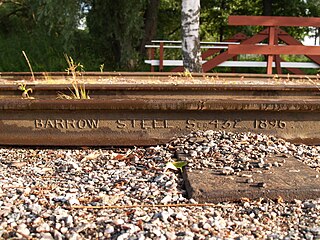
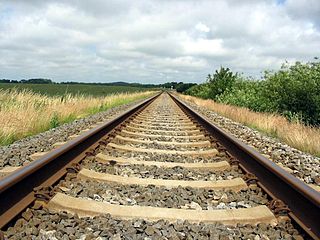
A railway track or railroad track, also known as permanent way or simply track, is the structure on a railway or railroad consisting of the rails, fasteners, railroad ties and ballast, plus the underlying subgrade. It enables trains to move by providing a dependable surface for their wheels to roll upon. Tracks where electric trains or electric trams run are equipped with an electrification system such as an overhead electrical power line or an additional electrified rail. Early tracks were constructed with wooden or cast iron rails, and wooden or stone sleepers; since the 1870s, rails have almost universally been made from steel.

History of the railway track History of rail transport tracks

The railway track or permanent way is the elements of railway lines: generally the pairs of rails typically laid on the sleepers or ties embedded in ballast, intended to carry the ordinary trains of a railway. It is described as permanent way because in the earlier days of railway construction, contractors often laid a temporary track to transport spoil and materials about the site; when this work was substantially completed, the temporary track was taken up and the permanent way installed.

Railroad tie Support for the rails in railroad tracks

A railroad tie, crosstie, railway tie or railway sleeper is a rectangular support for the rails in railroad tracks. Generally laid perpendicular to the rails, ties transfer loads to the track ballast and subgrade, hold the rails upright and keep them spaced to the correct gauge.

The Bristol and Gloucester Railway was a railway company opened in 1844 to run services between Bristol and Gloucester. It was built on the 7 ftBrunel gauge, but it was acquired in 1845 by the 4 ft 8+12 instandard gauge Midland Railway, which also acquired the Birmingham and Gloucester Railway at the same time.

High-speed railway track construction is the process by which Lignes à Grandes Vitesses, the land on which TGV trains are to run, is prepared for their use, involving carving the track bed and laying the track. This construction technique is used both for the French TGV network and other TGV-based networks outside of France.

Loughor Viaduct

The Loughor railway viaduct carries the West Wales Line across the River Loughor. It is adjacent, and runs parallel to, the Loughor road bridge. The 1880 viaduct was granted Grade II listed building status. Before it was demolished in early 2013, the viaduct was the last remaining timber viaduct designed by Isambard Kingdom Brunel.

The West Cornwall Railway was a railway company in Cornwall, Great Britain, formed in 1846 to construct a railway between Penzance and Truro. It purchased the existing Hayle Railway, and improved its main line, and built new sections between Penzance and Hayle, and between Redruth and Truro, and opened throughout in 1852.

The South Wales Railway was a main line railway which opened in stages from 1850, connecting the Great Western Railway from Gloucester to South Wales. It was constructed on the broad gauge. An original aspiration was to reach Fishguard to engender an Irish ferry transit and transatlantic trade, but the latter did not materialise for many years, and never became an important sector of the business. Neyland was the western terminus of the line until 1906.

Rail profile Cross sectional shape of a railway rail

The rail profile is the cross sectional shape of a railway rail, perpendicular to its length.

Railways in Plymouth Overview of railways in Plymouth, Devon, England

The network of railways in Plymouth, Devon, England, was developed by companies affiliated to two competing railways, the Great Western Railway and the London and South Western Railway. At their height two main lines and three branch lines served 28 stations in the Plymouth area, but today just six stations remain in use.

Concrete sleeper

A concrete sleeper or concrete tie is a type of railway sleeper or railroad tie made out of steel reinforced concrete.

Barlow rail

Barlow rail was a rolled rail section used on early railways. It has wide flaring feet and was designed to be laid direct on the ballast, without requiring sleepers. It was widely adopted on lightly trafficked railways, but was ultimately unsuccessful because of maintenance difficulties.

Culm Valley Light Railway

The Culm Valley Light Railway was a standard gauge branch railway that operated in the English county of Devon. It ran for just under 7+12 miles (12.1 km) from Tiverton Junction station on the Bristol to Exeter line, through the Culm valley to Hemyock.

Iberian-gauge railways Railway track gauge (1668 mm)

Iberian gauge is a track gauge of 1,668 mm, most extensively used by the railways of Spain and Portugal. This is the second-widest gauge in regular use anywhere in the world. The Indian gauge, 5 ft 6 in, is 8 mm wider.

Rail fastening system Rail-tie/sleeper binding mechanism

A rail fastening system is a means of fixing rails to railroad ties or sleepers. The terms rail anchors, tie plates, chairs and track fasteners are used to refer to parts or all of a rail fastening system. The components of a rail fastening system may also be known collectively as other track material, or OTM for short. Various types of fastening have been used over the years.

Ladder track is a type of railway track in which the track is laid on longitudinal supports with transverse connectors holding the two rails at the correct gauge distance. Modern ladder track can be considered a development of baulk road, which supported rails on longitudinal wooden sleepers. Synonyms include longitudinal beam track.

Bogie bolster wagon British railway term for a wagon for long thin cargoes

A bogie bolster wagon is a British railway term for a wagon designed to carry long thin cargoes such as timber or rails and other steel sections. The sides and ends are minimal and there is no roof. The load is carried longitudinally and borne by three or more bolsters fixed transversely. The load is constrained sideways by movable metal stanchions fitted into the ends of the bolsters, and secured with chains and shackles.

References

  1. MacDermot, E T (1927). History of the Great Western Railway. Vol. 1 (1833–1863) (1 ed.). London: Great Western Railway.
  2. 1 2 3 4 5 6 7 8 Mann, JW (1993). "Great Western Permanent Way". Broadsheet. Broad Gauge Society (29): 10–16.
  3. Slinn, JN (1978). Great Western Way. Woking: Historical Model Railway Society.
  4. 1 2 MacDermot, E T (1931). History of the Great Western Railway. Vol. 2 (1863–1921) (1 ed.). London: Great Western Railway.
  5. Brown, Derek (2005). "Seven Feet Gauge Breakwater Locomotives (Introduction)". Industrial Railway Record. Industrial Railway Society (183): 225–236. ISSN   0537-5347.
  6. Brown, Derek (2006). "Seven Feet Gauge Breakwater Locomotives (South Africa)". Industrial Railway Record. Industrial Railway Society (185): 336–343. ISSN   0537-5347.