A tailplane, also known as a horizontal stabiliser, is a small lifting surface located on the tail (empennage) behind the main lifting surfaces of a fixed-wing aircraft as well as other non-fixed-wing aircraft such as helicopters and gyroplanes. Not all fixed-wing aircraft have tailplanes. Canards, tailless and flying wing aircraft have no separate tailplane, while in V-tail aircraft the vertical stabiliser, rudder, and the tail-plane and elevator are combined to form two diagonal surfaces in a V layout.

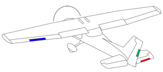
An aileron is a hinged flight control surface usually forming part of the trailing edge of each wing of a fixed-wing aircraft. Ailerons are used in pairs to control the aircraft in roll, which normally results in a change in flight path due to the tilting of the lift vector. Movement around this axis is called 'rolling' or 'banking'.

Aeroelasticity is the branch of physics and engineering studying the interactions between the inertial, elastic, and aerodynamic forces occurring while an elastic body is exposed to a fluid flow. The study of aeroelasticity may be broadly classified into two fields: static aeroelasticity dealing with the static or steady state response of an elastic body to a fluid flow, and dynamic aeroelasticity dealing with the body's dynamic response.

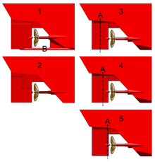
In flight dynamics a spin is a special category of stall resulting in autorotation about the aircraft's longitudinal axis and a shallow, rotating, downward path approximately centred on a vertical axis. Spins can be entered intentionally or unintentionally, from any flight attitude if the aircraft has sufficient yaw while at the stall point. In a normal spin, the wing on the inside of the turn stalls while the outside wing remains flying. It is possible for both wings to stall, but the angle of attack of each wing, and consequently its lift and drag, are different.

Aircraft flight control surfaces are aerodynamic devices allowing a pilot to adjust and control the aircraft's flight attitude.
A conventional fixed-wing aircraft flight control system (AFCS) consists of flight control surfaces, the respective cockpit controls, connecting linkages, and the necessary operating mechanisms to control an aircraft's direction in flight. Aircraft engine controls are also considered as flight controls as they change speed.

Elevators are flight control surfaces, usually at the rear of an aircraft, which control the aircraft's pitch, and therefore the angle of attack and the lift of the wing. The elevators are usually hinged to the tailplane or horizontal stabilizer. They may be the only pitch control surface present, and are sometimes located at the front of the aircraft or integrated into a rear "all-moving tailplane", also called a slab elevator or stabilator.

The empennage, also known as the tail or tail assembly, is a structure at the rear of an aircraft that provides stability during flight, in a way similar to the feathers on an arrow. The term derives from the French language verb empenner which means "to feather an arrow". Most aircraft feature an empennage incorporating vertical and horizontal stabilising surfaces which stabilise the flight dynamics of yaw and pitch, as well as housing control surfaces.
Aircraft flight mechanics are relevant to fixed wing and rotary wing (helicopters) aircraft. An aeroplane, is defined in ICAO Document 9110 as, "a power-driven heavier than air aircraft, deriving its lift chiefly from aerodynamic reactions on surface which remain fixed under given conditions of flight".
Trim tabs are small surfaces connected to the trailing edge of a larger control surface on a boat or aircraft, used to control the trim of the controls, i.e. to counteract hydro- or aerodynamic forces and stabilise the boat or aircraft in a particular desired attitude without the need for the operator to constantly apply a control force. This is done by adjusting the angle of the tab relative to the larger surface.

A servo tab is a small hinged device installed on an aircraft control surface to assist the movement of the control surfaces. Introduced by the German firm Flettner, servo tabs were formerly known as Flettner tabs. Servo tabs are not true servomechanisms, as they do not employ negative feedback to keep the control surfaces in a desired position; they only provide a mechanical advantage to the pilot.
A vertical stabilizer or tail fin is the static part of the vertical tail of an aircraft. The term is commonly applied to the assembly of both this fixed surface and one or more movable rudders hinged to it. Their role is to provide control, stability and trim in yaw. It is part of the aircraft empennage, specifically of its stabilizers.

An aircraft stabilizer is an aerodynamic surface, typically including one or more movable control surfaces, that provides longitudinal (pitch) and/or directional (yaw) stability and control. A stabilizer can feature a fixed or adjustable structure on which any movable control surfaces are hinged, or it can itself be a fully movable surface such as a stabilator. Depending on the context, "stabilizer" may sometimes describe only the front part of the overall surface.
Adverse yaw is the natural and undesirable tendency for an aircraft to yaw in the opposite direction of a roll. It is caused by the difference in lift and drag of each wing. The effect can be greatly minimized with ailerons deliberately designed to create drag when deflected upward and/or mechanisms which automatically apply some amount of coordinated rudder. As the major causes of adverse yaw vary with lift, any fixed-ratio mechanism will fail to fully solve the problem across all flight conditions and thus any manually operated aircraft will require some amount of rudder input from the pilot in order to maintain coordinated flight.

An aircraft in flight is free to rotate in three dimensions: yaw, nose left or right about an axis running up and down; pitch, nose up or down about an axis running from wing to wing; and roll, rotation about an axis running from nose to tail. The axes are alternatively designated as vertical, lateral, and longitudinal respectively. These axes move with the vehicle and rotate relative to the Earth along with the craft. These definitions were analogously applied to spacecraft when the first crewed spacecraft were designed in the late 1950s.
In flight dynamics, longitudinal stability is the stability of an aircraft in the longitudinal, or pitching, plane. This characteristic is important in determining whether an aircraft pilot will be able to control the aircraft in the pitching plane without requiring excessive attention or excessive strength.

A flight control mode or flight control law is a computer software algorithm that transforms the movement of the yoke or joystick, made by an aircraft pilot, into movements of the aircraft control surfaces. The control surface movements depend on which of several modes the flight computer is in. In aircraft in which the flight control system is fly-by-wire, the movements the pilot makes to the yoke or joystick in the cockpit, to control the flight, are converted to electronic signals, which are transmitted to the flight control computers that determine how to move each control surface to provide the aircraft movement the pilot ordered.
The Junkers J 29 was a two-seat, single-engined experimental training monoplane, built in Germany in 1925. Its significance is that it was the first aircraft to fly and test the Junkers Doppelflügel control surfaces used very successfully on the later Junkers Ju 52.

The Caudron C.25 was a large, three-engined, biplane airliner, designed and built in France soon after the end of World War I. Its enclosed cabin could accommodate up to eighteen passengers.

The Naleszkiewicz JN 1 was an experimental tailless sailplane designed in Poland to explore the aerodynamic properties of a proposed powered tailless aircraft. It proved hard to fly and a crash led to its abandonment after only a few months of limited testing.