Resistance thermometers, also called resistance temperature detectors (RTDs), are sensors that use the electrical resistance of a substance (such as platinum) to measure temperature. Many RTD elements consist of a length of fine wire wrapped around a heat-resistant ceramic or glass core but other constructions are also used. The RTD wire is typically platinum (Pt), nickel (Ni), or copper (Cu). The material has an accurate temperature–resistance relationship which is used to provide an indication of temperature. As RTD elements are fragile, they are often housed in protective probes called thermowells. RTDs have higher accuracy and repeatability[a] than thermocouples, which is why they are slowly replacing them in industrial applications below 600°C.[1]
Common RTD sensing elements for biomedical application constructed of platinum (Pt), nickel (Ni), or copper (Cu) have a repeatable[b]resistance versus temperature relationship (R vs T) and operating temperature range. The R vs T relationship is defined as the amount of resistance change of the sensor per degree of temperature change.[1] The relative change in resistance (temperature coefficient of resistance) varies only slightly over the useful range of the sensor.[citation needed]
Platinum was proposed by Sir William Siemens as an element for a resistance temperature detector at the Bakerian lecture in 1871:[2] it is a noble metal and has the most stable resistance–temperature relationship over the largest temperature range.
Nickel elements have a limited temperature range because the temperature coefficient of resistance changes at temperatures over 300°C (572°F).
Copper has a very linear resistance–temperature relationship; however, copper oxidizes at moderate temperatures and cannot be used over 150°C (302°F).[citation needed]
The significant characteristic of metals used as resistive elements is the linear approximation of the resistance versus temperature relationship between 0 and 100°C. This temperature coefficient of resistance is denoted by α and is usually given in units of Ω/(Ω·°C):[citation needed]
where
is the resistance of the sensor at 0 °C,
is the resistance of the sensor at 100 °C.
Pure platinum has α = 0.003925 Ω/(Ω·°C) in the 0 to 100°C range and is used in the construction of laboratory-grade RTDs. [citation needed] Conversely, two widely recognized standards for industrial RTDs IEC 60751 and ASTM E-1137 specify α = 0.00385 Ω/(Ω·°C). Before these standards were widely adopted, several different α values were used. It is still possible to find older probes that are made with platinum that have α = 0.003916 Ω/(Ω·°C) and 0.003902 Ω/(Ω·°C).[citation needed]
These different α values for platinum are achieved by doping – carefully introducing impurities, which become embedded in the lattice structure of the platinum and result in a different R vs. T curve and hence α value.[citation needed]
Calibration
To characterize the R vs T relationship of any RTD over a temperature range that represents the planned range of use, calibration must be performed at temperatures other than 0°C and 100°C. This is necessary to meet calibration requirements. Although RTDs are considered to be linear in operation, it must be proven that they are accurate with regard to the temperatures with which they will actually be used (see details in Comparison calibration option). Two common calibration methods are the fixed-point method and the comparison method.[citation needed]
Fixed-point calibration
is used for the highest-accuracy calibrations by national metrology laboratories.[3] It uses the triple point, freezing point or melting point of pure substances (such as water, zinc and tin) and argon to generate a known and repeatable temperature. These cells allow the user to reproduce actual conditions of the ITS-90 temperature scale. Fixed-point calibrations provide extremely accurate calibrations (within ±0.001°C). A common fixed-point calibration method for industrial-grade probes is the ice bath. The equipment is inexpensive, easy to use, and can accommodate several sensors at once. The ice point is designated as a secondary standard because its accuracy is ±0.005°C (±0.009°F), compared to ±0.001°C (±0.0018°F) for primary fixed points.
Comparison calibrations
is commonly used with secondary standard platinum resistance thermometers and industrial RTDs.[4] The thermometers being calibrated are compared to calibrated thermometers by means of a bath whose temperature is uniformly stable. Unlike fixed-point calibrations, comparisons can be made at any temperature between −100°C and 500°C (−148°F to 932°F). This method might be more cost-effective, since several sensors can be calibrated simultaneously with automated equipment. These electrically heated and well-stirred baths use silicone oils and molten salts as the medium for the various calibration temperatures.
Element types
The three main categories of RTD sensors are thin-film, wire-wound, and coiled elements. While these types are the ones most widely used in industry, other more exotic shapes are used; for example, carbonresistors are used at ultra-low temperatures (−273°C to −173°C).[5]
Carbon resistor elements
are cheap and widely used. They have very reproducible results at low temperatures. They are the most reliable over extremely wide range of temperatures. They generally do not suffer from significant hysteresis or strain gauge effects.
Strain-free elements
SPRT (Standard Platinum Resistance Thermometer) glass capsule – RTD use a wire coil minimally supported within a sealed housing filled with an inert gas (such as argon). These sensors work up to 961.78°C (1,763.20°F) and are used in the SPRTs (Standard Platinum Resistance Thermometers) that define ITS-90.[clarification needed] They consist of platinum wire loosely coiled over a support structure, so the element is free to expand and contract with temperature. They are very susceptible to shock and vibration, as the loops of platinum can sway back and forth, causing deformation.
Thin-film elements
Thin-film PRT (platinum resistance thermometer) have a sensing element that is formed by depositing a very thin layer of resistive material, normally platinum, on a ceramic substrate (plating). This layer is usually just 10 to 100 ångströms (1 to 10 nanometers) thick.[6] This film is then coated with an epoxy or glass that helps protect the deposited film and also acts as a strain relief for the external lead wires. Disadvantages of this type are that they are not as stable as their wire-wound or coiled counterparts. They also can only be used over a limited temperature range due to the different expansion rates of the substrate and resistive deposited giving a "strain gauge" effect that can be seen in the resistive temperature coefficient. These elements work with temperatures to 300°C (572°F) without further packaging, but can operate up to 600°C (1,112°F) when suitably encapsulated in glass or ceramic. Special high-temperature RTD elements can be used up to 900°C (1,652°F) with the right encapsulation.
Wire-wound elements
Wire-wound PRT can have greater accuracy, especially for wide temperature ranges. The coil diameter provides a compromise between mechanical stability and allowing expansion of the wire to minimize strain and consequential drift. The sensing wire is wrapped around an insulating mandrel or core. The winding core can be round or flat, but must be an electrical insulator. The coefficient of thermal expansion of the winding core material is matched to the sensing wire to minimize any mechanical strain. This strain on the element wire will result in a thermal measurement error. The sensing wire is connected to a larger wire, usually referred to as the element lead or wire. This wire is selected to be compatible with the sensing wire, so that the combination does not generate an emf that would distort the thermal measurement. These elements work with temperatures to 660°C.
Coiled elements
Coil-element PRT have largely replaced wire-wound elements in industry. This design has a wire coil that can expand freely over temperature, held in place by some mechanical support, which lets the coil keep its shape. This “strain free” design allows the sensing wire to expand and contract free of influence from other materials; in this respect it is similar to the SPRT, the primary standard upon which ITS-90 is based, while providing the durability necessary for industrial use. The basis of the sensing element is a small coil of platinum sensing wire. This coil resembles a filament in an incandescent light bulb. The housing or mandrel is a hard fired ceramic oxide tube with equally spaced bores that run transverse to the axes. The coil is inserted in the bores of the mandrel and then packed with a very finely ground ceramic powder. = This permits the sensing wire to move, while still remaining in good thermal contact with the process. These elements work with temperatures to 850°C.
The current international standard that specifies tolerance and the temperature-to-electrical resistance relationship for platinum resistance thermometers (PRTs) is IEC 60751:2008; ASTM E1137 is also used in the United States. By far the most common devices used in industry have a nominal resistance of 100 ohms at 0°C and are called Pt100 sensors ("Pt" is the symbol for platinum, "100" for the resistance in ohms at 0°C). It is also possible to get Pt1000 sensors, where 1000 is for the resistance in ohms at 0°C. The sensitivity of a standard 100Ω sensor is a nominal 0.385 Ω/°C. RTDs with a sensitivity of 0.375 and 0.392Ω/°C, as well as a variety of others, are also available.
"Pt200" redirects here. For the isotope of platinum (Pt-200 or 200Pt), see platinum-200.
The platinum detecting wire needs to be kept free of contamination to remain stable. A platinum wire or film is supported on a former in such a way that it gets minimal differential expansion or other strains from its former, yet is reasonably resistant to vibration. RTD assemblies made from iron or copper are also used in some applications. Commercial platinum grades exhibit a temperature coefficient of resistance 0.00385/°C (0.385%/°C) (European Fundamental Interval).[7] The sensor is usually made to have a resistance of 100Ω at 0°C. This is defined in BS EN 60751:1996 (taken from IEC 60751:1995). The American Fundamental Interval is 0.00392/°C,[8] based on using a purer grade of platinum than the European standard. The American standard is from the Scientific Apparatus Manufacturers Association (SAMA), who are no longer in this standards field. As a result, the "American standard" is hardly the standard even in the US.
Lead-wire resistance can also be a factor; adopting three- and four-wire, instead of two-wire, connections can eliminate connection-lead resistance effects from measurements (see below); three-wire connection is sufficient for most purposes and is an almost universal industrial practice. Four-wire connections are used for the most precise applications.
Advantages and limitations
The advantages of platinum resistance thermometers include:
High accuracy
Low drift
Wide operating range
Suitability for precision applications.
Limitations:
RTDs in industrial applications are rarely used above 660°C. At temperatures above 660°C it becomes increasingly difficult to prevent the platinum from becoming contaminated by impurities from the metal sheath of the thermometer. This is why laboratory standard thermometers replace the metal sheath with a glass construction. At very low temperatures, say below −270°C (3K), because there are very few phonons, the resistance of an RTD is mainly determined by impurities and boundary scattering and thus basically independent of temperature. As a result, the sensitivity of the RTD is essentially zero and therefore not useful. [citation needed]
Compared to thermistors, platinum RTDs are less sensitive to small temperature changes and have a slower response time. However, thermistors have a smaller temperature range and stability.
RTDs vs thermocouples
The two most common ways of measuring temperatures for industrial applications are with resistance temperature detectors (RTDs) and thermocouples. The choice between them is typically determined by four factors.
Temperature
If process temperatures are between −200 and 500°C (−328.0 and 932.0°F), an industrial RTD is the preferred option. Thermocouples have a range of −180 to 2,320°C (−292.0 to 4,208.0°F),[9] so for temperatures above 500°C (932°F) it is the contact temperature measurement device commonly found in physics laboratories.
Response time
If the process requires a very fast response to temperature changes (fractions of a second as opposed to seconds), then a thermocouple is the best choice. Time response is measured by immersing the sensor in water moving at 1m/s (3.3ft/s) with a 63.2% step change.
Size
A standard RTD sheath is 3.175 to 6.35mm (0.1250 to 0.2500in) in diameter; sheath diameters for thermocouples can be less than 1.6mm (0.063in).
Accuracy and stability requirements
If a tolerance of 2°C is acceptable and the highest level of repeatability is not required, a thermocouple will serve. RTDs are capable of higher accuracy and can maintain stability for many years, while thermocouples can drift within the first few hours of use.
Construction
These elements nearly always require insulated leads attached. PVC, silicone rubber or PTFE insulators are used at temperatures below about 250°C. Above this, glass fibre or ceramic are used. The measuring point, and usually most of the leads, require a housing or protective sleeve, often made of a metal alloy that is chemically inert to the process being monitored. Selecting and designing protection sheaths can require more care than the actual sensor, as the sheath must withstand chemical or physical attack and provide convenient attachment points.
The RTD construction design may be enhanced to handle shock and vibration by including compacted magnesium oxide (MgO) powder inside the sheath. MgO is used to isolate the conductors from the external sheath and from each other. MgO is used due to its dielectric constant, rounded grain structure, high-temperature capability, and its chemical inertness.
Wiring configurations
Two-wire configuration
Two-wire resistance thermometer
The simplest resistance-thermometer configuration uses two wires. It is only used when high accuracy is not required, as the resistance of the connecting wires is added to that of the sensor, leading to errors of measurement. This configuration allows use of 100meters of cable. This applies equally to balanced bridge (Wheatstone bridge) and fixed bridge system.
For a balanced bridge usual setting is with R2 = R1, and R3 around the middle of the range of the RTD. So for example, if we are going to measure between 0 and 100°C (32 and 212°F), RTD resistance will range from 100 Ω to 138.5 Ω. We would choose R3 = 120 Ω. In that way we get a small measured voltage in the bridge.
Three-wire configuration
Three-wire RTD Wheatstone bridge
In order to minimize the effects of the lead resistances, a three-wire configuration can be used. The suggested setting for the configuration shown, is with R1 = R2, and R3 around the middle of the range of the RTD. Looking at the Wheatstone bridge circuit shown, the voltage drop on the lower left hand side is V_rtd + V_lead, and on the lower righthand side is V_R3 + V_lead, therefore the bridge voltage (V_b) is the difference, V_rtd − V_R3. The voltage drop due to the lead resistance has been cancelled out. This always applies if R1=R2, and R1, R2 >> RTD, R3. R1 and R2 can serve the use of limiting the current through the RTD, for example for a Pt100, limiting to 1mA, and 5V, would suggest a limiting resistance of approximately R1 = R2 = 5/0.001 = 5,000 Ohms.
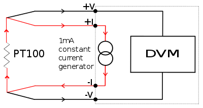
The four-wire resistance configuration increases the accuracy of measurement of resistance. Four-terminal sensing eliminates voltage drop in the measuring leads as a contribution to error. To increase accuracy further, any residual thermoelectric voltages generated by different wire types or screwed connections are eliminated by reversal of the direction of the 1mA current and the leads to the DVM (digital voltmeter). The thermoelectric voltages will be produced in one direction only. By averaging the reversed measurements, the thermoelectric error voltages are cancelled out.[citation needed]
The highest-accuracy of all PRTs are the Ultra Precise Platinum Resistance Thermometers (UPRTs). This accuracy is achieved at the expense of durability and cost. The UPRT elements are wound from reference-grade platinum wire. Internal lead wires are usually made from platinum, while internal supports are made from quartz or fused silica. The sheaths are usually made from quartz or sometimes Inconel, depending on temperature range. Larger-diameter platinum wire is used, which drives up the cost and results in a lower resistance for the probe (typically 25.5 Ω). UPRTs have a wide temperature range (−200°C to 1000°C) and are approximately accurate to ±0.001°C over the temperature range. UPRTs are only appropriate for laboratory use.
Standard Platinum Resistance Thermometers (Standard PRTs or SPRTs)
Another classification of laboratory PRTs is Standard Platinum Resistance Thermometers (Standard PRTs or SPRTs). They are constructed like the UPRT, but the materials are more cost-effective. SPRTs commonly use reference-grade, high-purity smaller-diameter platinum wire, metal sheaths and ceramic type insulators. Internal lead wires are usually a nickel-based alloy. Standard PRTs are more limited in temperature range (−200°C to 500°C) and are approximately accurate to ±0.03°C over the temperature range.
Industrial PRTs
Industrial PRTs are designed to withstand industrial environments. They can be almost as durable as a thermocouple. Depending on the application, industrial PRTs can use thin-film or coil-wound elements. The internal lead wires can range from PTFE-insulated stranded nickel-plated copper to silver wire, depending on the sensor size and application. Sheath material is typically stainless steel; higher-temperature applications may demand Inconel. Other materials are used for specialized applications.
In 1871 Carl Wilhelm Siemens invented the Platinum Resistance Temperature Detector and presented a three-term interpolation formula. Siemens’ RTD rapidly fell out of favour due to the instability of the temperature reading. Hugh Longbourne Callendar developed the first commercially successful platinum RTD in 1885.
A 1971 paper by Eriksson, Keuther, and Glatzel identified six noble metal alloys (63Pt37Rh, 37Pd63Rh, 26Pt74Ir, 10Pd90Ir, 34Pt66Au, 14Pd86Au) with approximately linear resistance temperature characteristics. The alloy 63Pt37Rh is similar to the readily available 70Pt30Rh alloy wire used in thermocouples.[11]
The Space Shuttle made extensive use of platinum resistance thermometers. The only in-flight shutdown of a Space Shuttle Main Engine– mission STS-51F– was caused by multiple failures of RTDs which had become brittle and unreliable due to multiple heat-and-cool cycles. (The failures of the sensors falsely suggested that a fuel pump was critically overheating, and the engine was automatically shut down.) Following the engine failure incident, the RTDs were replaced with thermocouples.[12]
Standard resistance thermometer data
Temperature sensors are usually supplied with thin-film elements. The resistance elements are rated in accordance with BS EN 60751:2008 as:
Tolerance class
Valid range
F 0.3
−50 to +500°C
F 0.15
−30 to +300°C
F 0.1
0 to +150°C
Resistance-thermometer elements functioning up to 1000°C can be supplied. The relation between temperature and resistance is given by the Callendar–Van Dusen equation:
Here is the resistance at temperature T, is the resistance at 0°C, and the constants (for an α = 0.00385 platinum RTD) are:
Since the B and C coefficients are relatively small, the resistance changes almost linearly with the temperature.
For positive temperature, solution of the quadratic equation yields the following relationship between temperature and resistance:
Then for a four-wire configuration with a 1 mA precision current source[13] the relationship between temperature and measured voltage is
Temperature-dependent resistances for various popular resistance thermometers
1 2 Hughes, Thomas A. (2002). Measurement and Control Basics, resources for measurement and control series. (3:e upplagan). Research Triangle Park, North Carlolina: The Instrumentation, Systems and Automation Society (ISA). pp.173–175. ISBN978-1556177644.
↑ L. J. Eriksson, F. W. Keuther, and J.J. Glatzel (1971). “A Linear Resistance Thermometer,” Proceedings of the Fifth Temperature Symposium, Washington, DC, 1971, pp. 989–995
↑ Wings in Orbit: Scientific and Engineering Legacies of the Space Shuttle, page 251
↑ Strouse, G. F. (2008). Standard Platinum Resistance Thermometer Calibrations from the Ar TP to the Ag FP. Gaithersburg, MD: National Institute of Standards and Technology.
This page is based on this Wikipedia article Text is available under the CC BY-SA 4.0 license; additional terms may apply. Images, videos and audio are available under their respective licenses.