Time stretch analog-to-digital converter

Last updated

The time-stretch analog-to-digital converter (TS-ADC), [1] [2] [3] also known as the time stretch enhanced recorder (TiSER), is an analog-to-digital converter (ADC) system that has the capability of digitizing very high bandwidth signals that cannot be captured by conventional electronic ADCs. [4] Alternatively, it is also known as the photonic time stretch (PTS) digitizer, [5] since it uses an optical frontend. It relies on the process of time-stretch, which effectively slows down the analog signal in time (or compresses its bandwidth) before it can be digitized by a slow electronic ADC.

Contents

Background

There is a huge demand for very high speed analog-to-digital converters (ADCs), as they are needed for test and measurement equipment in laboratories and in high speed data communications systems.[ citation needed ] Most of the ADCs are based purely on electronic circuits, which have limited speeds and add a lot of impairments, limiting the bandwidth of the signals that can be digitized and the achievable signal-to-noise ratio. In the TS-ADC, this limitation is overcome by time-stretching the analog signal, which effectively slows down the signal in time prior to digitization. By doing so, the bandwidth (and carrier frequency) of the signal is compressed. Electronic ADCs that would have been too slow to digitize the original signal, can now be used to capture this slowed down signal.

Operation principle

A time-stretch analog-to-digital converter (with a stretch factor of 4) is shown. The original analog signal is time-stretched and segmented with the help of a time-stretch preprocessor (generally on optical frontend). Slowed down segments are captured by conventional electronic ADCs. The digitized samples are rearranged to obtain the digital representation of the original signal. Tsadc block diagram.png
A time-stretch analog-to-digital converter (with a stretch factor of 4) is shown. The original analog signal is time-stretched and segmented with the help of a time-stretch preprocessor (generally on optical frontend). Slowed down segments are captured by conventional electronic ADCs. The digitized samples are rearranged to obtain the digital representation of the original signal.
Optical frontend for a time-stretch analog-to-digital converter is shown. The original analog signal is modulated over a chirped optical pulse (obtained by dispersing an ultra-short supercontinuum pulse from a mode-locked laser, MLL). Second dispersive medium stretches the optical pulse further. At the photodetector (PD) output, stretched replica of original signal is obtained. Pts preprocessor mwp link.png
Optical frontend for a time-stretch analog-to-digital converter is shown. The original analog signal is modulated over a chirped optical pulse (obtained by dispersing an ultra-short supercontinuum pulse from a mode-locked laser, MLL). Second dispersive medium stretches the optical pulse further. At the photodetector (PD) output, stretched replica of original signal is obtained.

The time-stretch processor, which is generally an optical frontend, stretches the signal in time. It also divides the signal into multiple segments using a filter, for example a wavelength division multiplexing (WDM) filter, to ensure that the stretched replica of the original analog signal segments do not overlap each other in time after stretching. The time-stretched and slowed down signal segments are then converted into digital samples by slow electronic ADCs. Finally, these samples are collected by a digital signal processor (DSP) and rearranged in a manner such that output data is the digital representation of the original analog signal. Any distortion added to the signal by the time-stretch preprocessor is also removed by the DSP.

An optical front-end is commonly used to accomplish this process of time-stretch. An ultrashort optical pulse (typically 100 to 200 femtoseconds long), also called a supercontinuum pulse, which has a broad optical bandwidth, is time-stretched by dispersing it in a highly dispersive medium (such as a dispersion compensating fiber). This process results in (an almost) linear time-to-wavelength mapping in the stretched pulse, because different wavelengths travel at different speeds in the dispersive medium. The obtained pulse is called a chirped pulse as its frequency is changing with time, and it is typically a few nanoseconds long. The analog signal is modulated onto this chirped pulse using an electro-optic intensity modulator. Subsequently, the modulated pulse is stretched further in the second dispersive medium which has much higher dispersion value. Finally, this obtained optical pulse is converted to electrical domain by a photodetector, giving the stretched replica of the original analog signal.

For continuous operation, a train of supercontinuum pulses is used. The chirped pulses arriving at the electro-optic modulator should be wide enough (in time) such that the trailing edge of one pulse overlaps the leading edge of the next pulse. For segmentation, optical filters separate the signal into multiple wavelength channels at the output of the second dispersive medium. For each channel, a separate photodetector and backend electronic ADC is used. Finally the output of these ADCs are passed on to the DSP which generates the desired digital output.

Impulse response of the photonic time-stretch (PTS) system

The PTS processor is based on specialized analog optical (or microwave photonic) fiber links [5] such as those used in cable TV distribution. While the dispersion of fiber is a nuisance in conventional analog optical links, time-stretch technique exploits it to slow down the electrical waveform in the optical domain. In the cable TV link, the light source is a continuous-wave (CW) laser. In PTS, the source is a chirped pulse laser.

Capture of a 95 GHz RF tone using the photonic time-stretch digitizer. The signal is captured at an effective sample rate of 10 terasamples per second. Tsadc 10Tsps.png
Capture of a 95 GHz RF tone using the photonic time-stretch digitizer. The signal is captured at an effective sample rate of 10 terasamples per second.

In a conventional analog optical link, dispersion causes the upper and lower modulation sidebands, foptical ± felectrical, to slip in relative phase. At certain frequencies, their beats with the optical carrier interfere destructively, creating nulls in the frequency response of the system. For practical systems the first null is at tens of GHz, which is sufficient for handling most electrical signals of interest. Although it may seem that the dispersion penalty places a fundamental limit on the impulse response (or the bandwidth) of the time-stretch system, it can be eliminated. The dispersion penalty vanishes with single-sideband modulation. [5] Alternatively, one can use the modulator’s secondary (inverse) output port to eliminate the dispersion penalty, [5] in much the same way as two antennas can eliminate spatial nulls in wireless communication (hence the two antennas on top of a WiFi access point). This configuration is termed phase-diversity. [6] Combining the complementary outputs using a maximal ratio combining (MRC) algorithm results in a transfer function with a flat response in the frequency domain. Thus, the impulse response (bandwidth) of a time-stretch system is limited only by the bandwidth of the electro-optic modulator, which is about 120 GHz—a value that is adequate for capturing most electrical waveforms of interest.

Extremely large stretch factors can be obtained using long lengths of fiber, but at the cost of larger loss—a problem that has been overcome by employing Raman amplification within the dispersive fiber itself, leading to the world’s fastest real-time digitizer. [7] Also, using PTS, capture of very high frequency signals with a world record resolution in 10-GHz bandwidth range has been achieved. [8]

Comparison with time lens imaging

Another technique, temporal imaging using a time lens, can also be used to slow down (mostly optical) signals in time. The time-lens concept relies on the mathematical equivalence between spatial diffraction and temporal dispersion, the so-called space-time duality. [9] A lens held at fixed distance from an object produces a magnified visible image. The lens imparts a quadratic phase shift to the spatial frequency components of the optical waves; in conjunction with the free space propagation (object to lens, lens to eye), this generates a magnified image. Owing to the mathematical equivalence between paraxial diffraction and temporal dispersion, an optical waveform can be temporally imaged by a three-step process of dispersing it in time, subjecting it to a phase shift that is quadratic in time (the time lens itself), and dispersing it again. Theoretically, a focused aberration-free image is obtained under a specific condition when the two dispersive elements and the phase shift satisfy the temporal equivalent of the classic lens equation. Alternatively, the time lens can be used without the second dispersive element to transfer the waveform’s temporal profile to the spectral domain, analogous to the property that an ordinary lens produces the spatial Fourier transform of an object at its focal points. [10]

In contrast to the time-lens approach, PTS is not based on the space-time duality – there is no lens equation that needs to be satisfied to obtain an error-free slowed-down version of the input waveform. Time-stretch technique also offers continuous-time acquisition performance, a feature needed for mainstream applications of oscilloscopes.

Another important difference between the two techniques is that the time lens requires the input signal to be subjected to high amount of dispersion before further processing. For electrical waveforms, the electronic devices that have the required characteristics: (1) high dispersion to loss ratio, (2) uniform dispersion, and (3) broad bandwidths, do not exist. This renders time lens not suitable for slowing down wideband electrical waveforms. In contrast, PTS does not have such a requirement. It was developed specifically for slowing down electrical waveforms and enable high speed digitizers.

Relation to phase stretch transform

The phase stretch transform or PST is a computational approach to signal and image processing. One of its utilities is for feature detection and classification. phase stretch transform is a spin-off from research on the time stretch dispersive Fourier transform. It transforms the image by emulating propagation through a diffractive medium with engineered 3D dispersive property (refractive index).

Application to imaging and spectroscopy

In addition to wideband A/D conversion, photonic time-stretch (PTS) is also an enabling technology for high-throughput real-time instrumentation such as imaging [11] and spectroscopy. [12] [13] The first artificial intelligence facilitated high-speed phase microscopy is demonstrated to improve the diagnosis accuracy of cancer cells out of blood cells by simultaneous measurement of phase and intensity spatial profiles. [14] The world's fastest optical imaging method called serial time-encoded amplified microscopy (STEAM) makes use of the PTS technology to acquire image using a single-pixel photodetector and commercial ADC. Wavelength-time spectroscopy, which also relies on photonic time-stretch technique, permits real-time single-shot measurements of rapidly evolving or fluctuating spectra.

Time stretch quantitative phase imaging (TS-QPI) is an imaging technique based on time-stretch technology for simultaneous measurement of phase and intensity spatial profiles. In time stretched imaging, the object’s spatial information is encoded in the spectrum of laser pulses within a pulse duration of sub-nanoseconds. Each pulse representing one frame of the camera is then stretched in time so that it can be digitized in real-time by an electronic analog-to-digital converter (ADC). The ultra-fast pulse illumination freezes the motion of high-speed cells or particles in flow to achieve blur-free imaging. [15] [16]

Related Research Articles

Analog-to-digital converter system that converts an analog signal, such as a sound picked up by a microphone or light entering a digital camera, into a digital signal; device converting a physical quantity to a digital number

In electronics, an analog-to-digital converter is a system that converts an analog signal, such as a sound picked up by a microphone or light entering a digital camera, into a digital signal. An ADC may also provide an isolated measurement such as an electronic device that converts an input analog voltage or current to a digital number representing the magnitude of the voltage or current. Typically the digital output is a two's complement binary number that is proportional to the input, but there are other possibilities.

A chirp is a signal in which the frequency increases (up-chirp) or decreases (down-chirp) with time. In some sources, the term chirp is used interchangeably with sweep signal. It is commonly used in sonar, radar, and laser, but has other applications, such as in spread-spectrum communications.

Digital-to-analog converter device that converts a digital signal into an analog signal

In electronics, a digital-to-analog converter is a system that converts a digital signal into an analog signal. An analog-to-digital converter (ADC) performs the reverse function.

Aliasing Effect that causes signals to become indistinguishable when sampled; often producing detectable aberrations

In signal processing and related disciplines, aliasing is an effect that causes different signals to become indistinguishable when sampled. It also often refers to the distortion or artifact that results when a signal reconstructed from samples is different from the original continuous signal.

Dispersion (optics) Dependence of phase velocity on frequency

In optics, dispersion is the phenomenon in which the phase velocity of a wave depends on its frequency. Media having this common property may be termed dispersive media. Sometimes the term chromatic dispersion is used for specificity. Although the term is used in the field of optics to describe light and other electromagnetic waves, dispersion in the same sense can apply to any sort of wave motion such as acoustic dispersion in the case of sound and seismic waves, in gravity waves, and for telecommunication signals along transmission lines or optical fiber.

Photonics Branch of physics related to the technical applications of light

Photonics is the physical science of light (photon) generation, detection, and manipulation through emission, transmission, modulation, signal processing, switching, amplification, and sensing. Though covering all light's technical applications over the whole spectrum, most photonic applications are in the range of visible and near-infrared light. The term photonics developed as an outgrowth of the first practical semiconductor light emitters invented in the early 1960s and optical fibers developed in the 1970s.

Sampling (signal processing) measurement of a signal at discrete time intervals

In signal processing, sampling is the reduction of a continuous-time signal to a discrete-time signal. A common example is the conversion of a sound wave to a sequence of samples.

In optics, an ultrashort pulse of light is an electromagnetic pulse whose time duration is of the order of a picosecond or less. Such pulses have a broadband optical spectrum, and can be created by mode-locked oscillators. They are commonly referred to as ultrafast events. Amplification of ultrashort pulses almost always requires the technique of chirped pulse amplification, in order to avoid damage to the gain medium of the amplifier.

In a mixed-signal system, a reconstruction filter, sometimes called an anti-imaging filter, is used to construct a smooth analog signal from a digital input, as in the case of a digital to analog converter (DAC) or other sampled data output device.

Optical resolution describes the ability of an imaging system to resolve detail in the object that is being imaged.

Slow light is the propagation of an optical pulse or other modulation of an optical carrier at a very low group velocity. Slow light occurs when a propagating pulse is substantially slowed down by the interaction with the medium in which the propagation takes place.

Multiphoton intrapulse interference phase scan (MIIPS) is a method used in ultrashort laser technology that simultaneously measures, and compensates femtosecond laser pulses using an adaptive pulse shaper. When an ultrashort laser pulse reaches a duration of less than a few hundred femtosecond, it becomes critical to characterize its duration, its temporal intensity curve, or its electric field as a function of time. Classical photodetectors measuring the intensity of light are still too slow to allow for a direct measurement, even with the fastest photodiodes or streak cameras.

Serial time-encoded amplified imaging/microscopy or stretched time-encoded amplified imaging/microscopy' (STEAM) is a fast real-time optical imaging method that provides MHz frame rate, ~100 ps shutter speed, and ~30 dB optical image gain. Based on the Photonic Time Stretch technique, STEAM holds world records for shutter speed and frame rate in continuous real-time imaging. STEAM employs the Photonic Time Stretch with internal Raman amplification to realize optical image amplification to circumvent the fundamental trade-off between sensitivity and speed that affects virtually all optical imaging and sensing systems. This method uses a single-pixel photodetector, eliminating the need for the detector array and readout time limitations. Avoiding this problem and featuring the optical image amplification for dramatic improvement in sensitivity at high image acquisition rates, STEAM's shutter speed is at least 1000 times faster than the state-of-the-art CCD and CMOS cameras. Its frame rate is 1000 times faster than fastest CCD cameras and 10-100 times faster than fastest CMOS cameras.

Time stretch dispersive Fourier transform (TS-DFT), otherwise known as time-stretch transform (TST), temporal Fourier transform or photonic time-stretch (PTS) is a spectroscopy technique that uses optical dispersion instead of a grating or prism to separate the light wavelengths and analyze the optical spectrum in real-time. It employs group-velocity dispersion (GVD) to transform the spectrum of a broadband optical pulse into a time stretched temporal waveform. It is used to perform Fourier transformation on an optical signal on a single shot basis and at high frame rates for real-time analysis of fast dynamic processes. It replaces a diffraction grating and detector array with a dispersive fiber and single-pixel detector, enabling ultrafast real-time spectroscopy and imaging. Its nonuniform variant, warped-stretch transform, realized with nonlinear group delay, offers variable-rate spectral domain sampling, as well as the ability to engineer the time-bandwidth product of the signal's envelope to match that of the data acquisition systems acting as an information gearbox.

An anamorphic stretch transform (AST) also referred to as warped stretch transform is a physics-inspired signal transform that emerged from time stretch dispersive Fourier transform. The transform can be applied to analog temporal signals such as communication signals, or to digital spatial data such as images. The transform reshapes the data in such a way that its output has properties conducive for data compression and analytics. The reshaping consists of warped stretching in the Fourier domain. The name "Anamorphic" is used because of the metaphoric analogy between the warped stretch operation and warping of images in anamorphosis and surrealist artworks.

Optical rogue waves

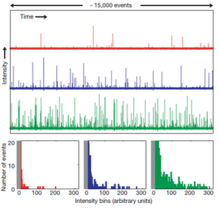
Optical rogue waves are rare pulses of light analogous to rogue or freak ocean waves. The term optical rogue waves was coined to describe rare pulses of broadband light arising during the process of supercontinuum generation—a noise-sensitive nonlinear process in which extremely broadband radiation is generated from a narrowband input waveform—in nonlinear optical fiber. In this context, optical rogue waves are characterized by an anomalous surplus in energy at particular wavelengths and/or an unexpected peak power. These anomalous events have been shown to follow heavy-tailed statistics, also known as L-shaped statistics, fat-tailed statistics, or extreme-value statistics. These probability distributions are characterized by long tails: large outliers occur rarely, yet much more frequently than expected from Gaussian statistics and intuition. Such distributions also describe the probabilities of freak ocean waves and various phenomena in both the man-made and natural worlds. Despite their infrequency, rare events wield significant influence in many systems. Aside from the statistical similarities, light waves traveling in optical fibers are known to obey the similar mathematics as water waves traveling in the open ocean, supporting the analogy between oceanic rogue waves and their optical counterparts. More generally, research has exposed a number of different analogies between extreme events in optics and hydrodynamic systems. A key practical difference is that most optical experiments can be done with a table-top apparatus, offer a high degree of experimental control, and allow data to be acquired extremely rapidly. Consequently, optical rogue waves are attractive for experimental and theoretical research and have become a highly studied phenomenon. The particulars of the analogy between extreme waves in optics and hydrodynamics may vary depending on the context, but the existence of rare events and extreme statistics in wave-related phenomena are common ground.

Phase stretch transform

Phase stretch transform (PST) is a computational approach to signal and image processing. One of its utilities is for feature detection and classification. PST is related to time stretch dispersive Fourier transform. It transforms the image by emulating propagation through a diffractive medium with engineered 3D dispersive property. The operation relies on symmetry of the dispersion profile and can be understood in terms of dispersive eigenfunctions or stretch modes. PST performs similar functionality as phase-contrast microscopy, but on digital images. PST can be applied to digital images and temporal data.

Photonic radar is a technique by which radar may be produced and analysed with the help of photonics rather than traditional RF techniques. The frequency of the radar is still in the RF, but lasers are used to create and analyse the RF signals with high precision. The name "photonic radar" is sometimes used to mean visible-spectrum range finding like Lidar.

Virtually imaged phased array Dispersive optical device

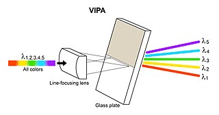
A virtually imaged phased array (VIPA) is an angular dispersive device that, like a prism or a diffraction grating, splits light into its spectral components. It works almost independently of polarization. In contrast to prisms or regular diffraction gratings, it has a much higher angular dispersion but has a smaller free spectral range. This aspect is similar to that of an Echelle grating which is usually used in reflection, since high diffraction orders are also used there. The VIPA can be a compact optical component with high wavelength resolving power.

Andrew Marc Weiner is an American electrical engineer, educator and researcher known for contributions to the fields of ultrafast optics and optical signal processing. He is the Scifres Family Distinguished Professor of Electrical and Computer Engineering at Purdue University.

References

  1. A. S. Bhushan, F. Coppinger, and B. Jalali, “Time-stretched analogue-to-digital conversion," Electronics Letters vol. 34, no. 9, pp. 839–841, April 1998.
  2. A. Fard, S. Gupta, and B. Jalali, "Photonic time-stretch digitizer and its extension to real-time spectroscopy and imaging," Laser & Photonics Reviews vol. 7, no. 2, pp. 207-263, March 2013.
  3. Y. Han and B. Jalali, “Photonic Time-Stretched Analog-to-Digital Converter: Fundamental Concepts and Practical Considerations," Journal of Lightwave Technology, Vol. 21, Issue 12, pp. 3085–3103, Dec. 2003.
  4. Mahjoubfar, Ata; Churkin, Dmitry V.; Barland, Stéphane; Broderick, Neil; Turitsyn, Sergei K.; Jalali, Bahram (June 2017). "Time stretch and its applications". Nature Photonics. 11 (6): 341–351. Bibcode:2017NaPho..11..341M. doi:10.1038/nphoton.2017.76. ISSN   1749-4885.
  5. 1 2 3 4 J. Capmany and D. Novak, “Microwave photonics combines two worlds," Nature Photonics1, 319-330 (2007).
  6. Yan Han, Ozdal Boyraz, Bahram Jalali, "Ultrawide-Band Photonic Time-Stretch A/D Converter Employing Phase Diversity," "IEEE TRANSACTIONS ON MICROWAVE THEORY AND TECHNIQUES" VOL. 53, NO. 4, APRIL 2005
  7. J. Chou, O. Boyraz, D. Solli, and B. Jalali, “Femtosecond real-time single-shot digitizer," Applied Physics Letters91, 161105 (2007).
  8. S. Gupta and B. Jalali, “Time-warp correction and calibration in photonic time-stretch analog-to-digital converter," Optics Letters33, 2674–2676 (2008).
  9. B. H. Kolner and M. Nazarathy, “Temporal imaging with a time lens," Optics Letters14, 630-632 (1989)
  10. J. W. Goodman, “Introduction to Fourier Optics," McGraw-Hill (1968).
  11. K. Goda, K.K. Tsia, and B. Jalali, "Serial time-encoded amplified imaging for real-time observation of fast dynamic phenomena," Nature 458, 1145–1149, 2009.
  12. D. R. Solli, J. Chou, and B. Jalali, "Amplified wavelength–time transformation for real-time spectroscopy," Nature Photonics 2, 48-51, 2008.
  13. J. Chou, D. Solli, and B. Jalali, "Real-time spectroscopy with subgigahertz resolution using amplified dispersive Fourier transformation," Applied Physics Letters 92, 111102, 2008.
  14. C. Chen, A. Mahjoubfar, & B. Jalali, “Deep Learning in Label-free Cell Classification," Scientific Reports 6, 21471 (2016) doi : 10.1038/srep21471.
  15. Chen, Claire Lifan; Mahjoubfar, Ata; Tai, Li-Chia; Blaby, Ian K.; Huang, Allen; Niazi, Kayvan Reza; Jalali, Bahram (2016). "Deep Learning in Label-free Cell Classification". Scientific Reports. 6: 21471. Bibcode:2016NatSR...621471C. doi:10.1038/srep21471. PMC   4791545 . PMID   26975219. published under CC BY 4.0 licensing
  16. Michaud, Sarah (5 April 2016). "Leveraging Big Data for Cell Imaging". Optics & Photonics News . Full text download available: The Optical Society . Retrieved 8 July 2016.

Further reading