Fixture (tool)

Last updated
A common type of fixture, used in materials tensile testing TH11-50kN-pincer-grip.jpg
A common type of fixture, used in materials tensile testing

A fixture is a work-holding or support device used in the manufacturing industry. [1] [2] Fixtures are used to securely locate (position in a specific location or orientation) and support the work, ensuring that all parts produced using the fixture will maintain conformity and interchangeability. Using a fixture improves the economy of production by allowing smooth operation and quick transition from part to part, reducing the requirement for skilled labor by simplifying how workpieces are mounted, and increasing conformity across a production run. [2]

Contents

Compared with a jig

A fixture differs from a jig in that when a fixture is used, the tool must move relative to the workpiece; a jig moves the piece while the tool remains stationary. [3]

Purpose

A fixture's primary purpose is to create a secure mounting point for a workpiece, allowing for support during operation and increased accuracy, precision, reliability, and interchangeability in the finished parts. It also serves to reduce working time by allowing quick set-up, and by smoothing the transition from part to part. [3] It frequently reduces the complexity of a process, allowing for unskilled workers to perform it and effectively transferring the skill of the tool maker to the unskilled worker. [2] Fixtures also allow for a higher degree of operator safety by reducing the concentration and effort required to hold a piece steady. [3]

Economically speaking the most valuable function of a fixture is to reduce labor costs. Without a fixture, operating a machine or process may require two or more operators; using a fixture can eliminate one of the operators by securing the workpiece. [4]

Design

These modular fixture components may be built into various arrangements to accommodate different workpieces Tooling fixtures.jpg
These modular fixture components may be built into various arrangements to accommodate different workpieces

Fixtures should be designed with economics in mind; the purpose of these devices is often to reduce costs, and so they should be designed in such a way that the cost reduction outweighs the cost of implementing the fixture. It is usually better, from an economic standpoint, for a fixture to result in a small cost reduction for a process in constant use, than for a large cost reduction for a process used only occasionally. [4]


Most fixtures have a solid component, affixed to the floor or to the body of the machine and considered immovable relative to the motion of the machining bit, and one or more movable components known as clamps. These clamps (which may be operated by many different mechanical means) allow workpieces to be easily placed in the machine or removed, and yet stay secure during operation. Many are also adjustable, allowing for workpieces of different sizes to be used for different operations. Fixtures must be designed such that the pressure or motion of the machining operation (usually known as the feed) is directed primarily against the solid component of the fixture. This reduces the likelihood that the fixture will fail, interrupting the operation and potentially causing damage to infrastructure, components, or operators. [5]

Fixtures may also be designed for very general or simple uses. These multi-use fixtures tend to be very simple themselves, often relying on the precision and ingenuity of the operator, as well as surfaces and components already present in the workshop, to provide the same benefits of a specially-designed fixture. Examples include workshop vises, adjustable clamps, and improvised devices such as weights and furniture.

Each component of a fixture is designed for one of two purposes: location or support.

Location

Locating components ensure the geometrical stability of the workpiece. They make sure that the workpiece rests in the correct position and orientation for the operation by addressing and impeding all the degrees of freedom the workpiece possesses. [6]

For locating workpieces, fixtures employ pins (or buttons), clamps, and surfaces. These components ensure that the workpiece is positioned correctly, and remains in the same position throughout the operation. Surfaces provide support for the piece, pins allow for precise location at low surface area expense, and clamps allow for the workpiece to be removed or its position adjusted. Locating pieces tend to be designed and built to very tight specifications. [7]

Support

In designing the locating parts of a fixture, only the direction of forces applied by the operation are considered, and not their magnitude. Locating parts technically support the workpiece, but do not take into account the strength of forces applied by the process and so are usually inadequate to actually secure the workpiece during operation. For this purpose, support components are used. [8]

To secure workpieces and prevent motion during operation, support components primarily use two techniques: positive stops and friction. A positive stop is any immovable component (such as a solid surface or pin) that, by its placement, physically impedes the motion of the workpiece. Support components are more likely to be adjustable than locating components, and normally do not press tightly on the workpiece or provide absolute location. [9]

Support components usually bear the brunt of the forces delivered during the operation. To reduce the chances of failure, support components are usually not also designed as clamps.

For example: 2 heavy metal parts are to be joined with screws and arc welding. Using a fixture will help secure the two separate parts in a designated area for the craftsman to complete the job easily & without the risk of injury.

Types of fixtures

Fixtures are usually classified according to the machine for which they were designed. The most common two are milling fixtures and drill fixtures. [10]

Milling fixtures

Milling operations tend to involve large, straight cuts that produce many chips and involve varying force. Locating and supporting areas must usually be large and very sturdy in order to accommodate milling operations; strong clamps are also a requirement. Due to the vibration of the machine, positive stops are preferred over friction for securing the workpiece. For high-volume automated processes, milling fixtures usually involve hydraulic or pneumatic clamps. [11] [12]

Drilling fixtures

Drilling fixtures cover a wider range of different designs and procedures than milling fixtures. Though workholding for drills is more often provided by jigs, fixtures are also used for drilling operations.

Two common elements of drilling fixtures are the hole and bushing. Holes are often designed into drilling fixtures, to allow space for the drill bit itself to continue through the workpiece without damaging the fixture or drill, or to guide the drill bit to the appropriate point on the workpiece. Bushings are simple bearing sleeves inserted into these holes to protect them and guide the drill bit. [13]

Because drills tend to apply force in only one direction, support components for drilling fixtures may be simpler. If the drill is aligned pointing down, the same support components may compensate for the forces of both the drill and gravity at once. However, though monodirectional, the force applied by drills tends to be concentrated on a very small area. Drilling fixtures must be designed carefully to prevent the workpiece from bending under the force of the drill. [14]

Welding fixtures

Welding fixtures are used to hold subcomponents of a welded assembly in place for fabrication together into one complete unit. These fixtures are often actuated using manual (hand) clamps or pneumatic clamps if paired with robotic automation. A robust robotic arc welding fixture is a part-holding tool used to constrain components for welding in an automated system. [15] Welding fixtures locate parts using these clamps to secure important aspects of the subcomponent, such as holes, slots, or datum surfaces.

Careful considerations must be made when designing welding fixtures. Proper clearance must be allowed for welding torch access. This can be especially difficult to accommodate if the torch is a large spot-welding gun. The welding fixture must be designed to allow all subcomponent parts to nest together properly to obtain the necessary amount of gap for fusion. Weld orientation is a paramount concern, as sloping or vertical welds can lead to weld drip, which will result in cratering and undercutting where the bead should blend into the base metals, resulting in a weak weld and a risk of cracking at the edge of the bead.

Similar build strategies are used for welding fixtures that are employed with milling fixtures and drilling fixtures. The weld torch is most often moved to the workpiece. Welding jigs, in comparison, are commonly used with pedestal welders and linear weld torches, moving the workpiece to the torch. Modular fixturing strategies can be deployed in production scenarios where a setup is needed for a run of the same part in a shorter period of time. Fixture plates and common workholding solutions are designed to accommodate these scenarios. [16]


See also

Notes

  1. Colvin & Haas 1938, p. 1.
  2. 1 2 3 Henriksen 1973, p. 1.
  3. 1 2 3 Colvin & Haas 1938, p. 3.
  4. 1 2 Colvin & Haas 1938, p. 4.
  5. Colvin & Haas 1938, p. 5.
  6. Henriksen 1973, p. 18.
  7. Henriksen 1973, Ch. 4.
  8. Henriksen 1973, p. 19.
  9. Henriksen 1973, Ch. 12.
  10. Henriksen 1973, p. 3.
  11. Henriksen 1973, Ch. 19.
  12. Colvin & Haas 1938, Ch. 11.
  13. Colvin & Haas 1938, Ch. 4.
  14. Colvin & Haas 1938, Ch. 10.
  15. "Robotic Gas Metal Arc Welding Fixtures". stryver.com. Stryver Manufacturing, Inc. Retrieved 21 January 2024.
  16. "A guide to modular fixturing in welding". thefabricator.com. The Fabricator. Retrieved 22 January 2024.

Related Research Articles

<span class="mw-page-title-main">Lathe</span> Machine tool which rotates the work piece on its axis

A lathe is a machine tool that rotates a workpiece about an axis of rotation to perform various operations such as cutting, sanding, knurling, drilling, deformation, facing, threading and turning, with tools that are applied to the workpiece to create an object with symmetry about that axis.

<span class="mw-page-title-main">Workbench</span>

A workbench is a sturdy table at which manual work is done. They range from simple flat surfaces to very complex designs that may be considered tools in themselves. Workbenches vary in size from tiny jewellers benches to the huge benches used by staircase makers. Almost all workbenches are rectangular in shape, often using the surface, corners and edges as flat/square and dimension standards. Design is as varied as the type of work for which the benches are used but most share these attributes:

<span class="mw-page-title-main">Metalworking</span> Process of making items from metal

Metalworking is the process of shaping and reshaping metals in order to create useful objects, parts, assemblies, and large scale structures. As a term, it covers a wide and diverse range of processes, skills, and tools for producing objects on every scale: from huge ships, buildings, and bridges, down to precise engine parts and delicate jewelry.

<span class="mw-page-title-main">Metal fabrication</span> Creation of metal structures

Metal fabrication is the creation of metal structures by cutting, bending and assembling processes. It is a value-added process involving the creation of machines, parts, and structures from various raw materials.

<span class="mw-page-title-main">Grinding machine</span> Machine tool used for grinding

A grinding machine, often shortened to grinder, is a power tool used for grinding. It is a type of machining using an abrasive wheel as the cutting tool. Each grain of abrasive on the wheel's surface cuts a small chip from the workpiece via shear deformation.

<span class="mw-page-title-main">Plasma cutting</span> Process

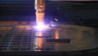
Plasma cutting is a process that cuts through electrically conductive materials by means of an accelerated jet of hot plasma. Typical materials cut with a plasma torch include steel, stainless steel, aluminum, brass and copper, although other conductive metals may be cut as well. Plasma cutting is often used in fabrication shops, automotive repair and restoration, industrial construction, and salvage and scrapping operations. Due to the high speed and precision cuts combined with low cost, plasma cutting sees widespread use from large-scale industrial computer numerical control (CNC) applications down to small hobbyist shops.

<span class="mw-page-title-main">Collet</span> Type of chuck

A collet is a segmented sleeve, band or collar. One of the two radial surfaces of a collet is usually tapered and the other is cylindrical. The term collet commonly refers to a type of chuck that uses collets to hold either a workpiece or a tool but has other mechanical applications.

<span class="mw-page-title-main">Chuck (engineering)</span> Clamp used to hold an object with radial symmetry, especially a cylinder

A chuck is a specialized type of clamp used to hold an object with radial symmetry, especially a cylinder. In a drill, a mill and a transmission, a chuck holds the rotating tool; in a lathe, it holds the rotating workpiece.

<span class="mw-page-title-main">Turning</span> Machining process

Turning is a machining process in which a cutting tool, typically a non-rotary tool bit, describes a helix toolpath by moving more or less linearly while the workpiece rotates.

<span class="mw-page-title-main">Lathe center</span>

A lathe center, often shortened to center, is a tool that has been ground to a point to accurately position a workpiece on an axis. They usually have an included angle of 60°, but in heavy machining situations an angle of 75° is used.

<span class="mw-page-title-main">Metal lathe</span> Machine tool used to remove material from a rotating workpiece

In machining, a metal lathe or metalworking lathe is a large class of lathes designed for precisely machining relatively hard materials. They were originally designed to machine metals; however, with the advent of plastics and other materials, and with their inherent versatility, they are used in a wide range of applications, and a broad range of materials. In machining jargon, where the larger context is already understood, they are usually simply called lathes, or else referred to by more-specific subtype names. These rigid machine tools remove material from a rotating workpiece via the movements of various cutting tools, such as tool bits and drill bits.

<span class="mw-page-title-main">Mitre box</span> Woodworking tool used to guide a saw

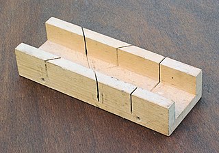
A mitre box or miter box is a wood working appliance used to guide a hand saw for making precise cuts, usually 45° mitre cuts. Traditional mitre boxes are simple in construction and made of wood, while adjustable mitre boxes are made of metal and can be adjusted for cutting any angle from 45° to 90°.

<span class="mw-page-title-main">Rotary table</span> Tool used in metalworking

A rotary table is a precision work positioning device used in metalworking. It enables the operator to drill or cut work at exact intervals around a fixed axis. Some rotary tables allow the use of index plates for indexing operations, and some can also be fitted with dividing plates that enable regular work positioning at divisions for which indexing plates are not available. A rotary fixture used in this fashion is more appropriately called a dividing head.

<span class="mw-page-title-main">Boring (manufacturing)</span> Process of enlarging an already-drilled hole with a single-point cutting tool

In machining, boring is the process of enlarging a hole that has already been drilled by means of a single-point cutting tool, such as in boring a gun barrel or an engine cylinder. Boring is used to achieve greater accuracy of the diameter of a hole, and can be used to cut a tapered hole. Boring can be viewed as the internal-diameter counterpart to turning, which cuts external diameters.

<span class="mw-page-title-main">Tool and die maker</span> Class of machinist in manufacturing

Tool and die makers are highly skilled crafters working in the manufacturing industries. Tool and die makers work primarily in toolroom environments—sometimes literally in one room but more often in an environment with flexible, semipermeable boundaries from production work. They are skilled artisans (craftspeople) who typically learn their trade through a combination of academic coursework and with substantial period of on-the-job training that is functionally an apprenticeship. They make jigs, fixtures, dies, molds, machine tools, cutting tools, gauges, and other tools used in manufacturing processes.

<span class="mw-page-title-main">Centerless grinding</span> Machining process

Centerless grinding is a machining process that uses abrasive cutting to remove material from a workpiece. Centerless grinding differs from centered grinding operations in that no spindle or fixture is used to locate and secure the workpiece; the workpiece is secured between two rotary grinding wheels, and the speed of their rotation relative to each other determines the rate at which material is removed from the workpiece.

<span class="mw-page-title-main">Jig (tool)</span> Custom-made tool used to control the location and/or motion of another tool

A jig is a type of custom-made tool used to control the location and/or motion of parts or other tools.

<span class="mw-page-title-main">Fence (woodworking)</span> Woodworking tool part

A fence is a part of many woodworking tools; it is typically used to guide or secure a workpiece while it is being sawn, planed, routed or marked. Fences play an important role for both accuracy and safety. Fences are usually straight and vertical, and made from metal, wood or plastic.

Notching is a metal-cutting process used on sheet-metal or thin bar-stock, sometimes on angle sections or tube. A shearing or punching process is used in a press, so as to cut vertically down and perpendicular to the surface, working from the edge of a work-piece. Sometimes the goal is merely the notch itself, but usually this is a precursor to some other process: such as bending a corner in sheet or joining two tubes at a tee joint, notching one to fit closely to the other.

A drill bushing, also known as a jig bushing, is a tool used in metalworking jigs to guide cutting tools, most commonly drill bits. Other tools that are commonly used in a drill bushing include counterbores, countersinks, and reamers. They are designed to guide, position, and support the cutting tool.

References