Expansion chamber

Last updated
Scooter exhaust with expansion chamber and silencer Scooter exhaust.jpg
Scooter exhaust with expansion chamber and silencer

On a two-stroke engine, an expansion chamber or tuned pipe is a tuned exhaust system used to enhance its power output by improving its volumetric efficiency.

Contents

History

Direct comparison between different types of exhausts for the two-stroke engine, on the left you can see the engine and its exhaust, in the center the progression curves of the pressures (effective pressure in atmospheres) to the exhaust port (detection area highlighted in red), on the right the power curves of the various drains.
A) Traditional discharge with constant section
B) Discharge with divergent section
C) Resonant expansion chamber with expansion chamber, in the power graph the influence of the exhaust back pressure valve is also highlighted Studio scarico 2T (compato).svg
Direct comparison between different types of exhausts for the two-stroke engine, on the left you can see the engine and its exhaust, in the center the progression curves of the pressures (effective pressure in atmospheres) to the exhaust port (detection area highlighted in red), on the right the power curves of the various drains.
A) Traditional discharge with constant section
B) Discharge with divergent section
C) Resonant expansion chamber with expansion chamber, in the power graph the influence of the exhaust back pressure valve is also highlighted

Expansion chambers were invented and successfully manufactured by Limbach, a German engineer, in 1938, to economize fuel in two stroke engines. Germany was running short of petrol, which was at that stage produced using coal and sewage transformation. An unexpected bonus was that the two stroke engines using tuned exhausts produced far more power than if running with a normal silencer. After the end of the second world war, some time passed before the concept was re-developed by East German Walter Kaaden during the Cold War. They first appeared in the west on Japanese motorcycles after East German motorcycle racer Ernst Degner defected to the west while racing for MZ in the 1961 Swedish Grand Prix. He later passed his knowledge to Japan's Suzuki. [1] [2]

How it works

The high pressure gas exiting the cylinder initially flows in the form of a "wavefront" as all disturbances in fluids do. The exhaust gas pushes its way into the pipe which is already occupied by gas from previous cycles, pushing that gas ahead and causing a wave front. Once the gas flow stops, the wave continues, passing the energy to the next gas down stream and so on to the end of the pipe. If this wave encounters any change in cross section or temperature it will reflect a portion of its strength in the opposite direction to its travel. For example, a strong acoustic wave encountering an increase in area will reflect a weaker acoustic wave in the opposite direction. A strong acoustic wave encountering a decrease in area will reflect a strong acoustic wave in the opposite direction. The basic principle is described in wave dynamics. An expansion chamber makes use of this phenomenon by varying its diameter (cross section) and length to cause these reflections to arrive back at the cylinder at the desired time in the cycle.


There are three main parts to the expansion cycle.

Blowdown

When the descending piston first exposes the exhaust port on the cylinder wall, the exhaust flows out powerfully due to its pressure (without assistance from the expansion chamber) so the diameter/area over the length of the first portion of the pipe is constant or near constant with a divergence of 0 to 2 degrees which preserves wave energy. This section of the system is called the "header pipe" (the exhaust port length is considered part of the header pipe for measurement purposes). By keeping the header pipe diameter near constant, the energy in the wave is preserved because there is no expansion needed until later in the cycle. The flow leaving the cylinder during most of the blowdown process is sonic or supersonic, and therefore no wave could travel back into the cylinder against that flow.

Transfer

Once the exhaust pressure has fallen to near-atmospheric level, the piston uncovers the transfer ports. At this point energy from the expansion chamber can be used to aid the flow of fresh mixture into the cylinder. To do this, the expansion chamber is increased in diameter so that the out-going acoustic wave (created by the combustion process) creates a reflected vacuum (negative pressure) wave that returns to the cylinder. This part of the chamber is called the divergent (or diffuser) section and it diverges at 7 to 9 degrees. It may be made up of more than one diverging cone depending on requirements. The vacuum wave arrives in the cylinder during the transfer cycle and helps suck in fresh mixture from the crankcase into the cylinder, and/or prevent the suction of exhaust gases into the crankcase (due to crankcase vacuum). [3] However, the wave may also suck fresh mixture out the exhaust port into the header of the expansion chamber. This effect is mitigated by the port-blocking wave.

Port blocking

When the transfer is complete, the piston is on the compression stroke but the exhaust port is still open, an unavoidable problem with the two stroke piston port design. To help prevent the piston pushing fresh mixture out the open exhaust port the strong acoustic wave (produced by the combustion) from the expansion chamber is timed to arrive during the beginning of the compression stroke. The port blocking wave is created by reducing the diameter of the chamber. This is called the convergent section (or baffle cone). The outgoing acoustic wave hits the narrowing convergent section and reflects back a strong series of acoustic pulses to the cylinder. They arrive in time to block the exhaust port, still open during the beginning of the compression stroke and push back into the cylinder any fresh mixture drawn out into the header of the expansion chamber. The convergent section is made to converge at 16 to 25 degrees, depending on requirements.

Combined with the acoustic wave there is a general rise in pressure in the chamber caused by deliberately restricting the outlet with a small tube called the stinger, which acts as a bleeder, emptying the chamber during the compression/power stroke to have it ready for the next cycle. The stinger's length and inside diameter are based on 0.59 to 0.63x the header pipe diameter and its length is equal to 12 times its diameter, depending on the results to be achieved. In a well designed tuned exhaust system, the total increase in pressure is in any case much less than the one produced by a muffler. An erroneous sizing of the stinger will lead either to poor performance (too big or too short) or to excessive heat (too small or too long) which will damage the engine.

Complicating factors

The detailed operation of expansion chambers in practice is not as straightforward as the fundamental process described above. Waves traveling back up the pipe encounter the divergent section in reverse and reflect a portion of their energy back out. Temperature variations in different parts of the pipe cause reflections and changes in the local speed of sound. Sometimes these secondary wave reflections can inhibit the desired goal of more power.

It is useful to keep in mind that although the waves traverse the entire expansion chamber over each cycle, the actual gases leaving the cylinder during a particular cycle do not. The gas flows and stops intermittently and the wave continues on to the end of the pipe. The hot gases leaving the port form a "slug" which fills the header pipe and remains there for the duration of that cycle. This causes a high temperature zone in the head pipe which is always filled with the most recent and hottest gas. Because this area is hotter, the speed of sound and thus the speed of the waves that travel through it are increased. During the next cycle that slug of gas will be pushed down the pipe by the next slug to occupy the next zone and so on. The volume this "slug" occupies constantly varies according to throttle position and engine speed. It is only the wave energy itself that traverses the whole pipe during a single cycle. The actual gas leaving the pipe during a particular cycle was created two or three cycles earlier. This is why exhaust gas sampling on two stroke engines is done with a special valve right in the exhaust port. The gas exiting the stinger has had too much resident time and mixing with gas from other cycles causing errors in analysis.

Expansion chambers almost always have turns and curves built into them to accommodate their fit within the engine bay. Gases and waves do not behave in the same way when encountering turns. Waves travel by reflecting and spherical radiation. Turns causes a loss in the sharpness of the wave forms and therefore must be kept to a minimum to avoid unpredictable losses.

Calculations used to design expansion chambers take into account only the primary wave actions. This is usually fairly close but errors can occur due to these complicating factors.

See also

Related Research Articles

Two-stroke engine

A two-strokeengine is a type of internal combustion engine that completes a power cycle with two strokes of the piston during only one crankshaft revolution. This is in contrast to a "four-stroke engine", which requires four strokes of the piston to complete a power cycle during two crankshaft revolutions. In a two-stroke engine, the end of the combustion stroke and the beginning of the compression stroke happen simultaneously, with the intake and exhaust functions occurring at the same time.

Otto cycle Thermodynamic cycle for spark ignition piston engines

An Otto cycle is an idealized thermodynamic cycle that describes the functioning of a typical spark ignition piston engine. It is the thermodynamic cycle most commonly found in automobile engines.

Four-stroke engine

A four-strokeengine is an internal combustion (IC) engine in which the piston completes four separate strokes while turning the crankshaft. A stroke refers to the full travel of the piston along the cylinder, in either direction. The four separate strokes are termed:

  1. Intake: Also known as induction or suction. This stroke of the piston begins at top dead center (T.D.C.) and ends at bottom dead center (B.D.C.). In this stroke the intake valve must be in the open position while the piston pulls an air-fuel mixture into the cylinder by producing vacuum pressure into the cylinder through its downward motion. The piston is moving down as air is being sucked in by the downward motion against the piston.
  2. Compression: This stroke begins at B.D.C, or just at the end of the suction stroke, and ends at T.D.C. In this stroke the piston compresses the air-fuel mixture in preparation for ignition during the power stroke (below). Both the intake and exhaust valves are closed during this stage.
  3. Combustion: Also known as power or ignition. This is the start of the second revolution of the four stroke cycle. At this point the crankshaft has completed a full 360 degree revolution. While the piston is at T.D.C. the compressed air-fuel mixture is ignited by a spark plug or by heat generated by high compression, forcefully returning the piston to B.D.C. This stroke produces mechanical work from the engine to turn the crankshaft.
  4. Exhaust: Also known as outlet. During the exhaust stroke, the piston, once again, returns from B.D.C. to T.D.C. while the exhaust valve is open. This action expels the spent air-fuel mixture through the exhaust valve.
Brayton cycle Thermodynamic cycle

The Brayton cycle is a thermodynamic cycle named after George Brayton that describes the workings of a constant-pressure heat engine. The original Brayton engines used a piston compressor and piston expander, but more modern gas turbine engines and airbreathing jet engines also follow the Brayton cycle. Although the cycle is usually run as an open system, it is conventionally assumed for the purposes of thermodynamic analysis that the exhaust gases are reused in the intake, enabling analysis as a closed system.

Volumetric efficiency (VE) in internal combustion engine engineering is defined as the ratio of the mass density of the air-fuel mixture drawn into the cylinder at atmospheric pressure to the mass density of the same volume of air in the intake manifold. The term is also used in other engineering contexts, such as hydraulic pumps and electronic components.

Exhaust manifold

In automotive engineering, an exhaust manifold collects the exhaust gases from multiple cylinders into one pipe. The word manifold comes from the Old English word manigfeald and refers to the folding together of multiple inputs and outputs.

Exhaust system The part of the internal combustion engine which conducts the hot exhaust gases away from the engine

An exhaust system is used to guide reaction exhaust gases away from a controlled combustion inside an engine or stove. The entire system conveys burnt gases from the engine and includes one or more exhaust pipes. Depending on the overall system design, the exhaust gas may flow through one or more of:

Crankcase

A crankcase is the housing for the crankshaft in a reciprocating internal combustion engine. In most modern engines, the crankcase is integrated into the engine block.

The two-stroke power valve system is an improvement to a conventional two-stroke engine that gives a high power output over a wider RPM range.

In the context of an internal combustion engine, the term stroke has the following related meanings

Back pressure is a resistance or force opposing the desired flow of fluid through pipes, leading to friction loss and pressure drop. The term back pressure is a misnomer, as pressure is a scalar quantity, so it has a magnitude but no direction. The fluid is what is directed, tending to flow away from high-pressure regions and toward low-pressure regions. If the low-pressure space is more high-pressure than intended or the high-pressure space is more low-pressure than intended, this opposes the desired flow and reduces the discharge. Similarly, bending or other operations on a pipe can reduce flow rate.

Hot-bulb engine

The hot-bulb engine is a type of internal combustion engine in which fuel ignites by coming in contact with a red-hot metal surface inside a bulb, followed by the introduction of air (oxygen) compressed into the hot-bulb chamber by the rising piston. There is some ignition when the fuel is introduced, but it quickly uses up the available oxygen in the bulb. Vigorous ignition takes place only when sufficient oxygen is supplied to the hot-bulb chamber on the compression stroke of the engine.

The split-cycle engine is a type of internal combustion engine.

Schnuerle porting

Schnuerle porting is a system to improve efficiency of a valveless two-stroke engine by giving better scavenging. The intake and exhaust ports cut in the cylinder wall are shaped to give a more efficient transfer of intake and exhaust gases.

The term six-stroke engine has been applied to a number of alternative internal combustion engine designs that attempt to improve on traditional two-stroke and four-stroke engines. Claimed advantages may include increased fuel efficiency, reduced mechanical complexity and/or reduced emissions. These engines can be divided into two groups based on the number of pistons that contribute to the six strokes.

Scavenging (engine)

Scavenging is the process of replacing the exhaust gas in a cylinder of an internal combustion engine with the fresh air/fuel mixture for the next cycle. If scavenging is incomplete, the remaining exhaust gases can cause improper combustion for the next cycle, leading to reduced power output.

The Kadenacy effect is an effect of pressure-waves in gases. It is named after Michel Kadenacy who obtained a French patent for an engine utilizing the effect in 1933. There are also European and US patents. In simple terms, the momentum of the exhaust gas leaving the cylinder of an internal combustion engine creates a pressure-drop in the cylinder which assists the flow of a fresh charge of air, or fuel-air mixture, into the cylinder. The effect can be maximized by careful design of the inlet and exhaust passages.

Internal combustion engines come in a wide variety of types, but have certain family resemblances, and thus share many common types of components.

Tuned exhaust

In an internal combustion engine, the geometry of the exhaust system can be optimised ("tuned") to maximise the power output of the engine. Tuned exhausts are designed so that reflected pressure waves arrive at the exhaust port at a particular time in the combustion cycle.

Internal combustion engine Engine in which the combustion of a fuel occurs with an oxidizer in a combustion chamber

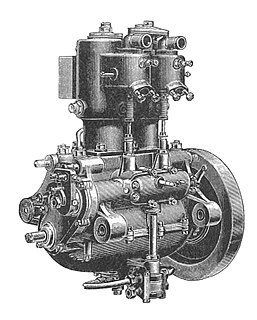
An internal combustion engine (ICE) is a heat engine in which the combustion of a fuel occurs with an oxidizer in a combustion chamber that is an integral part of the working fluid flow circuit. In an internal combustion engine, the expansion of the high-temperature and high-pressure gases produced by combustion applies direct force to some component of the engine. The force is applied typically to pistons, turbine blades, rotor or a nozzle. This force moves the component over a distance, transforming chemical energy into useful work. This replaced the external combustion engine for applications where weight or size of the engine is important.

References

  1. "Suzuki Motorcycle History: History of Suzuki". Motorcycle.com. Archived from the original on 2011-02-02.
  2. Oxley, Mat (2010), Stealing Speed: The Biggest Spy Scandal in Motorsport History, Haynes Publishing Group, ISBN   1-84425-975-7
  3. Forrest, Michael. "How an Expansion Chamber Works" . Retrieved 2016-06-07.