Cylinder head porting refers to the process of modifying the intake and exhaust ports of an internal combustion engine to improve their air flow. Cylinder heads, as manufactured, are usually suboptimal for racing applications due to being designed for maximum durability. Ports can be modified for maximum power, minimum fuel consumption, or a combination of the two, and the power delivery characteristics can be changed to suit a particular application.
When a modification is decided upon through testing with an air flow bench, the original port wall material can be reshaped by hand with die grinders or by numerically controlledmilling machines. For major modifications the ports must be welded up or similarly built up to add material where none existed.
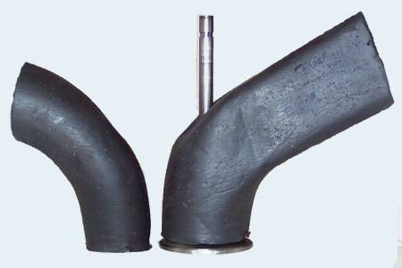
A port before and after modifications, exaggerated for illustrative purposes. The general idea of improving port flow is that a straighter pipe and gentler curves provide more peak power. This type of modification is commonly referred to as "increasing the downdraft angle", and is limited by mechanical constraints such as engine bay height, the amount of material in the parent casting, or the relocation of valve gear to accommodate the longer valve stem.A mold of the suboptimally designed ports of a Ford two-liter head for use in Formula 2000 racing. It is shown as manufactured with the intake port on the right.
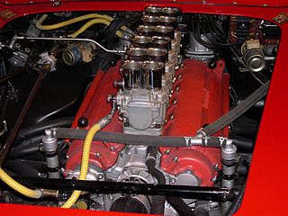
The Ford two-liter F2000 engine in stock trim equipped with the head shown above was capable of delivering 115 horsepower at 5500 rpm for a BMEP of 136 psi.
Port molds of a highly developed 500 cubic inch aftermarket Pro Stock racing head. Note the height and straightness of the ports, particularly the exhaust port on the left. This design is based on a cylinder head casting purpose-built for racing modifications. The head is supplied with small ports with ample material everywhere for porting specialists to shape to their requirements without having to weld on additional metal.
This aftermarketPro Stock racing head was used in an engine capable of 1300 horsepower at 9500 rpm with a BMEP of 238 psi. A BMEP of 238 puts it close to the limit for a naturally aspirated gas-burning engine. Naturally aspirated Formula One engines typically achieved BMEP values of 220 psi. Cam profiles, engine RPM, engine height constraints and other limitations contribute to the difference in engine power with the Ford unit as well, but the difference in port design is a major factor.
Port components
Parts of the port and their terminology
Wave dynamics
This highly simplified animation shows how air flows as waves in an intake system. Note the green "valve" opening and closing.
When the valve opens, the air doesn’t flow in, it decompresses into the low-pressure region below it. All the air on the upstream side of the moving disturbance boundary is completely isolated and unaffected by what happens on the downstream side. The air at the runner entrance does not move until the wave reaches all the way to the end. It is only then that the entire runner can begin to flow. Up until that point all that can happen is the higher pressure gas filling the volume of the runner decompresses or expands into the low-pressure region advancing up the runner. (Once the low-pressure wave reaches the open end of the runner it reverses sign, the onrushing air forces a high pressure wave down the runner. Not shown in this animation.)
Conversely, the closing of the valve does not immediately stop flow at the runner entrance, which continues completely unaffected until the signal that the valve closed reaches it. The closing valve causes a buildup of pressure that travels up the runner as a positive wave. The runner entrance continues to flow at full speed, forcing the pressure to rise until the signal reaches the entrance. This very considerable pressure rise can be seen on the graph below, it rises far above atmospheric pressure.
It is this phenomenon that enables the so-called “ram tuning” to occur, and it is what is being “tuned” by tuned intake and exhaust systems. The principle is the same as in the water hammer effect so well known to plumbers. The speed that the signal can travel is the speed of sound within the runner.
This is why port/runner volumes are so important; the volumes of successive parts of the port/runner control the flow during all transition periods. That is, any time a change occurs in the cylinder – whether positive or negative – such as when the piston reaches maximum speed. This point occurs at different points depending on the length of the connecting rod and the throw of the crank, and varies with the connecting rod ratio (rod/stroke). For normal automotive design this point is almost always between 69 and 79 degrees ATDC, with higher rod ratios favoring the later position. It only occurs at 1/2 stroke (90 degrees) with a connecting rod of infinite length.
The wave/flow activity in a real engine is vastly more complex than this but the principle is the same.
At first glance this wave travel might seem to be blindingly fast and not very significant but a few calculations show the opposite is true. In an intake runner at room temperature the sonic speed is about 1,100 feet per second (340m/s) and traverses a 12-inch (300mm) port/runner in 0.9 milliseconds. The engine using this system, running at 8500 rpm, takes a very considerable 46 crank degrees before any signal from the cylinder can reach the runner end (assuming no movement of the air in the runner). 46 degrees, during which nothing but the volume of the port/runner supplies the demands of the cylinder. This not only applies to the initial signal but to any and every change in the pressure or vacuum developed in the cylinder.
Using a shorter runner to reduce the delay is not feasible because, at the end of the cycle, the long runner now continues to flow at full speed disregarding the rising pressure in the cylinder and providing pressure to the cylinder when it is needed most. The runner length also controls the timing of the returning waves and cannot be altered. A shorter runner would flow earlier but also would die earlier while returning the positive waves much too quickly (tuned to a higher RPM) and those waves would be weaker. The key is to find the optimum balance of all the factors for the engine requirements.
Further complicating the system is the fact that the piston dome, the signal source, continually moves. First moving down the cylinder, thus increasing the distance the signal must travel. Then moving back up at the end of the intake cycle when the valve is still open past BDC. The signals coming from the piston dome, after the initial runner flow has been established, must fight upstream against whatever velocity has been developed at that instant, delaying it further. The signals developed by the piston do not have a clean path up the runner either. Large portions of it bounce off the rest of the combustion chamber and resonate inside the cylinder until an average pressure is reached. Also, temperature variations due to the changing pressures and absorption from hot engine parts cause changes in the local sonic velocity.
When the valve closes, it causes a pile up of gas giving rise to a strong positive wave that must travel up the runner. The wave activity in the port/runner does not stop but continues to reverberate for some time. When the valve next opens, the remaining waves influence the next cycle.
This graph shows the pressure taken from the valve end (blue line) and the runner entrance(red line) of an engine with a 7-inch (180mm) port/runner and running at 4500 rpm. Highlighted are two waves, a suction wave and a valve closing wave, seen and the valve end and runner entrance showing the signal delay. A lag of about 85 deg for the peak suction wave versus about 32 deg for the peak pressure wave. A difference of some 53 deg due to the movement of the gas and piston position.
The graph above shows the intake runner pressure over 720 crank degrees of an engine with a 7-inch (180mm) intake port/runner running at 4500 rpm, which is its torque peak (close to maximum cylinder filling and BMEP for this engine). The two pressure traces are taken from the valve end (blue) and the runner entrance (red). The blue line rises sharply as the intake valve closes. This causes a pile up of air, which becomes a positive wave reflected back up the runner and the red line shows that wave arriving at the runner entrance later. Note how the suction wave during cylinder filling is delayed even more by having to fight upstream against the inrushing air and the fact that the piston is further down the bore, increasing the distance.
The goal of tuning is to arrange the runners and valve timing so that there is a high-pressure wave in the port during the opening of the intake valve to get flow going quickly and then to have a second high pressure wave arrive just before valve closing so the cylinder fills as much as possible. The first wave is what is left in the runner from the previous cycle, while the second is primarily created during the current cycle by the suction wave changing sign at the runner entrance and arriving back at the valve in time for valve closing. The factors involved are often contradictory and requires a careful balancing act to work. When it does work, it is possible to see volumetric efficiencies of 140%, similar to that of a decent supercharger, but it only occurs over a limited RPM range.
Porting and polishing
It is popularly held that enlarging the ports to the maximum possible size and applying a mirror finish is what porting entails. However, that is not so. Some ports may be enlarged to their maximum possible size (in keeping with the highest level of aerodynamic efficiency), but those engines are highly developed, very-high-speed units where the actual size of the ports has become a restriction. Larger ports flow more fuel/air at higher RPMs but sacrifice torque at lower RPMs due to lower fuel/air velocity. A mirror finish of the port does not provide the increase that intuition suggests. In fact, within intake systems, the surface is usually deliberately textured to a degree of uniform roughness to encourage fuel deposited on the port walls to evaporate quickly. A rough surface on selected areas of the port may also alter flow by energizing the boundary layer, which can alter the flow path noticeably, possibly increasing flow. This is similar to what the dimples on a golf ball do. Flow bench testing shows that the difference between a mirror-finished intake port and a rough-textured port is typically less than 1%. The difference between a smooth-to-the-touch port and an optically mirrored surface is not measurable by ordinary means. Exhaust ports may be smooth-finished because of the dry gas flow and in the interest of minimizing exhaust by-product build-up. A 300- to 400-grit finish followed by a light buff is generally accepted to be representative of a near optimal finish for exhaust gas ports.
The reason that polished ports are not advantageous from a flow standpoint is that at the interface between the metal wall and the air, the air speed is zero (see boundary layer and laminar flow). This is due to the wetting action of the air and indeed all fluids. The first layer of molecules adheres to the wall and does not move significantly. The rest of the flow field must shear past, which develops a velocity profile (or gradient) across the duct. For surface roughness to impact flow appreciably, the high spots must be high enough to protrude into the faster-moving air toward the center. Only a very rough surface does this.
A developed velocity profile in a duct that shows why polished surfaces have little effect on flow. The air speed at the wall interface is zero regardless of how smooth it is.
Two-stroke porting
In addition to all the considerations given to a four-stroke engine port, two-stroke engine ports have additional ones:
Scavenging quality/purity: The ports are responsible for sweeping as much exhaust out of the cylinder as possible and refilling it with as much fresh mixture as possible without a large amount of the fresh mixture also going out the exhaust. This takes careful and subtle timing and aiming of all the transfer ports.
Power band width: Since two-strokes are very dependent on wave dynamics, their power bands tend to be narrow. While struggling to get maximum power, care must always be taken to ensure that the power profile does not get too sharp and hard to control.
Time area: Two-stroke port duration is often expressed as a function of time/area. This integrates the continually changing open port area with the duration. Wider ports increase time/area without increasing duration while higher ports increase both.
Timing: In addition to time area, the relationship between all the port timings strongly determine the power characteristics of the engine.
Wave Dynamic considerations: Although four-strokes have this problem, two-strokes rely much more heavily on wave action in the intake and exhaust systems. The two-stroke port design has strong effects on the wave timing and strength.
Heat flow: The flow of heat in the engine is heavily dependent on the porting layout. Cooling passages must be routed around ports. Every effort must be made to keep the incoming charge from heating up but at the same time many parts are cooled primarily by that incoming fuel/air mixture. When ports take up too much space on the cylinder wall, the ability of the piston to transfer its heat through the walls to the coolant is hampered. As ports get more radical, some areas of the cylinder get thinner, which can then overheat.
Piston ring durability: A piston ring must ride on the cylinder wall smoothly with good contact to avoid mechanical stress and assist in piston cooling. In radical port designs, the ring has minimal contact in the lower stroke area, which can suffer extra wear. The mechanical shocks induced during the transition from partial to full cylinder contact can shorten the life of the ring considerably. Very wide ports allow the ring to bulge out into the port, exacerbating the problem.
Piston skirt durability: The piston must also contact the wall for cooling purposes but also must transfer the side thrust of the power stroke. Ports must be designed so that the piston can transfer these forces and heat to the cylinder wall while minimizing flex and shock to the piston.
Engine configuration: Engine configuration can be influenced by port design. This is primarily a factor in multi-cylinder engines. Engine width can be excessive for even two cylinder engines of certain designs. Rotary disk valve engines with wide sweeping transfers can be so wide as to be impractical as a parallel twin. The V-twin and fore-and-aft engine designs are used to control overall width.
Cylinder distortion: Engine sealing ability, cylinder, piston and piston ring life all depend on reliable contact between cylinder and piston/piston ring so any cylinder distortion reduces power and engine life. This distortion can be caused by uneven heating, local cylinder weakness, or mechanical stresses. Exhaust ports that have long passages in the cylinder casting conduct large amounts of heat to one side of the cylinder while on the other side the cool intake may be cooling the opposite side. The thermal distortion resulting from the uneven expansion reduces both power and durability although careful design can minimize the problem.
Combustion turbulence: The turbulence remaining in the cylinder after transfer persists into the combustion phase to help burning speed. Unfortunately, good scavenging flow is slower and less turbulent.
Methods
The die grinder is the stock in trade of the head porter and are used with a variety of carbide cutters, grinding wheels and abrasive cartridges. The complex and sensitive shapes required in porting necessitate a good degree of artistic skill with a hand tool.
Until recently, CNCmachining was used only to provide the basic shape of the port but hand finishing was usually still required because some areas of the port were not accessible to a CNC tool. New developments in CNC machining now allow this process to be fully automated with the assistance of CAD/CAM software. 5-Axis CNC controls using specialized fixtures like tilting rotary tables allow the cutting tool full access to the entire port. The combination of CNC and CAM software give the porter full control over the port shape and surface finish.
Measurement of the interior of the ports is difficult but must be done accurately. Sheet metal templates are made up, taking the shape from an experimental port, for both cross-sectional and lengthwise shape. Inserted in the port these templates are then used as a guide for shaping the final port. Even a slight error might cause a loss in flow so measurement must be as accurate as possible. Confirmation of the final port shape and automated replication of the port is now done using digitizing. Digitizing is where a probe scans the entire shape of the port collecting data that can then be used by CNC machine tools and CAD/CAM software programs to model and cut the desired port shape. This replication process usually produces ports that flow within 1% of each other. This kind of accuracy, repeatability, time has never before been possible. What used to take eighteen hours or more now takes less than three.
Summary
The internal aerodynamics involved in porting is counter-intuitive and complex. Successfully optimizing ports requires an air flow bench, a thorough knowledge of the principles involved, and engine simulation software.
Although a large portion of porting knowledge has been accumulated by individuals using "cut and try" methods over time, the tools and knowledge now exist to develop a porting design with a measure of certainty.
Related Research Articles
In engineering, the Miller cycle is a thermodynamic cycle used in a type of internal combustion engine. The Miller cycle was patented by Ralph Miller, an American engineer, U.S. patent 2,817,322 dated Dec 24, 1957. The engine may be two- or four-stroke and may be run on diesel fuel, gases, or dual fuel. It uses a supercharger or a turbocharger to offset the performance loss of the Atkinson cycle.
A two-strokeengine is a type of internal combustion engine that completes a power cycle with two strokes of the piston in one revolution of the crankshaft. A four-stroke engine requires four strokes of the piston to complete a power cycle in two crankshaft revolutions. In a two-stroke engine, the end of the combustion stroke and the beginning of the compression stroke happen simultaneously, with the intake and exhaust functions occurring at the same time.
A four-strokeengine is an internal combustion (IC) engine in which the piston completes four separate strokes while turning the crankshaft. A stroke refers to the full travel of the piston along the cylinder, in either direction. The four separate strokes are termed:
Intake: Also known as induction or suction. This stroke of the piston begins at top dead center (T.D.C.) and ends at bottom dead center (B.D.C.). In this stroke the intake valve must be in the open position while the piston pulls an air-fuel mixture into the cylinder by producing a partial vacuum in the cylinder through its downward motion.
Compression: This stroke begins at B.D.C, or just at the end of the suction stroke, and ends at T.D.C. In this stroke the piston compresses the air-fuel mixture in preparation for ignition during the power stroke (below). Both the intake and exhaust valves are closed during this stage.
Combustion: Also known as power or ignition. This is the start of the second revolution of the four stroke cycle. At this point the crankshaft has completed a full 360 degree revolution. While the piston is at T.D.C. the compressed air-fuel mixture is ignited by a spark plug or by heat generated by high compression, forcefully returning the piston to B.D.C. This stroke produces mechanical work from the engine to turn the crankshaft.
Exhaust: Also known as outlet. During the exhaust stroke, the piston, once again, returns from B.D.C. to T.D.C. while the exhaust valve is open. This action expels the spent air-fuel mixture through the exhaust port.
Volumetric efficiency (VE) in internal combustion engine engineering is defined as the ratio of the equivalent volume of the fresh air drawn into the cylinder during the intake stroke to the volume of the cylinder itself. The term is also used in other engineering contexts, such as hydraulic pumps and electronic components.
Variable valve timing (VVT) is the process of altering the timing of a valve lift event in an internal combustion engine, and is often used to improve performance, fuel economy or emissions. It is increasingly being used in combination with variable valve lift systems. There are many ways in which this can be achieved, ranging from mechanical devices to electro-hydraulic and camless systems. Increasingly strict emissions regulations are causing many automotive manufacturers to use VVT systems.
In automotive engineering, an exhaust manifold collects the exhaust gases from multiple cylinders into one pipe. The word manifold comes from the Old English word manigfeald and refers to the folding together of multiple inputs and outputs.
Engine braking occurs when the retarding forces within an internal combustion engine are used to slow down a motor vehicle, as opposed to using additional external braking mechanisms such as friction brakes or magnetic brakes.
An inlet manifold or intake manifold is the part of an internal combustion engine that supplies the fuel/air mixture to the cylinders. The word manifold comes from the Old English word manigfeald and refers to the multiplying of one (pipe) into many.
Reed valves are a type of check valve which restrict the flow of fluids to a single direction, opening and closing under changing pressure on each face. Modern versions often consist of flexible metal or composite materials.
Alfa Romeo Twin Spark (TS) technology was used for the first time in the Alfa Romeo Grand Prix car in 1914. In the early 1960s it was used in their race cars (GTA, TZ) to enable it to achieve a higher power output from its engines. And in the early and middle 1980s, Alfa Romeo incorporated this technology into their road cars to enhance their performance and to comply with stricter emission controls.
Manifold vacuum, or engine vacuum in a petrol engine is the difference in air pressure between the engine's intake manifold and Earth's atmosphere.
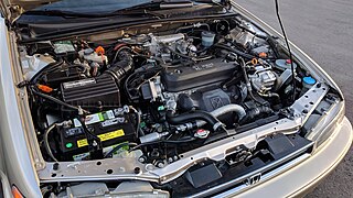
The Honda F-Series engine was considered Honda's "big block" SOHC inline four, though lower production DOHC versions of the F-series were built. It features a solid iron or aluminum open deck cast iron sleeved block and aluminum/magnesium cylinder head.
The two-stroke power valve system is an improvement to a conventional two-stroke engine that gives a high power output over a wider RPM range.
In a piston engine, the valve timing is the precise timing of the opening and closing of the valves. In an internal combustion engine those are usually poppet valves and in a steam engine they are usually slide valves or piston valves.
In a spark ignition internal combustion engine, ignition timing is the timing, relative to the current piston position and crankshaft angle, of the release of a spark in the combustion chamber near the end of the compression stroke.
Scavenging is the process of replacing the exhaust gas in a cylinder of an internal combustion engine with the fresh air/fuel mixture for the next cycle. If scavenging is incomplete, the remaining exhaust gases can cause improper combustion for the next cycle, leading to reduced power output.
The inertial supercharging effect is the increase of volumetric efficiency in the cylinder of an engine.
Internal combustion engines come in a wide variety of types, but have certain family resemblances, and thus share many common types of components.
In an internal combustion engine, the geometry of the exhaust system can be optimised ("tuned") to maximise the power output of the engine. Tuned exhausts are designed so that reflected pressure waves arrive at the exhaust port at a particular time in the combustion cycle.
An internal combustion engine is a heat engine in which the combustion of a fuel occurs with an oxidizer in a combustion chamber that is an integral part of the working fluid flow circuit. In an internal combustion engine, the expansion of the high-temperature and high-pressure gases produced by combustion applies direct force to some component of the engine. The force is typically applied to pistons, turbine blades, a rotor, or a nozzle. This force moves the component over a distance. This process transforms chemical energy into kinetic energy which is used to propel, move or power whatever the engine is attached to.
This page is based on this Wikipedia article Text is available under the CC BY-SA 4.0 license; additional terms may apply. Images, videos and audio are available under their respective licenses.