Swing-piston engine

Last updated

A swing-piston engine is a type of internal combustion engine in which the pistons move in a circular motion inside a ring-shaped "cylinder", moving closer and further from each other to provide compression and expansion. Generally two sets of pistons are used, geared to move in a fixed relationship as they rotate around the cylinder. In some versions the pistons oscillate around a fixed center, as opposed to rotating around the entire engine. The design has also been referred to as a oscillating piston engine, vibratory engine when the pistons oscillate instead of rotate, or toroidal engine based on the shape of the "cylinder".

Contents

Many swing-piston engines have been proposed, but none have been successful. Two attempts in about 2010 are the prototype American-made MYT engine [1] and prototype Russian ORE for use in the Yo-Mobile hybrid car. Both claimed high fuel efficiency and high power-to-weight ratio, but there have been no successful demonstrations of claimed efficiency or that the engines are durable enough for practical use.

Steam engines

Swing-piston engines were initially introduced during the 1820s as alternate steam engine designs, prior to the widespread introduction of the steam turbine. In these examples the "piston" is typically not cylindrical as in a modern internal combustion design, and is generally rectangular in cross-section as seen from the top, rotating in a flat disk "cylinder". From the side they are either flat plates or pie-wedge shaped. The term "swing-piston" is not entirely accurate in these cases, but the operating cycle is identical and is properly considered here.

The first known example was introduced by Elijah Galloway in 1829 for ship propulsion. It featured a single vane rotating through 270 degrees. It appears this version was never built, although a model still exists in the Science Museum. Galloway also designed a wide variety of pure rotary engines using vanes as well. [2]

A more serious attempt was the "Cambrian System" of John Jones in 1841. This design used two or three flat plates that were geared to move closer or further apart as the cycle continued. When the plates were at their closest point, steam was admitted between them using a valve, pushing them apart as the cycle continued. When the plates reached their maximum distance, an internal passage was uncovered that allowed the partially expanded steam to flow across the center of the device into the area on the other side of the vanes, which were now at their minimum distance. In this fashion the design was effectively a compound engine. [2]

Many variations followed, and a number of these saw limited use in the field. Notable among them was John Ericsson's design of 1843, which powered the USS Princeton, the United States' first screw-powered steamship. Charles Parsons examined the concept and appears to have produced two swing-piston engine designs before moving on to the steam turbine. The Roots brothers designed a swing-piston engine of a unique type, although they are better known for their supercharger design. [2]

Internal combustion

Figure 1 of US patent 2301667 showing a shaft, helical pistons and cams of Otto Lutz's engine US2301667-Figure1.png
Figure 1 of US patent 2301667 showing a shaft, helical pistons and cams of Otto Lutz's engine

It is unclear whether or not any internal combustion swing-piston engine has ever reached production, but the closest attempt appears to be the German World War II-era design by Otto Lutz  [ de ]. His design had six pistons in total, three each attached to two disks. The disks were geared to each other to form six chambers between the pistons, such that at any one time one set of three chambers were "close together" while the other set of three was "wide apart", varying between those two extremes as the disks rotated. The timing was arranged such that the chambers reached their "close together" point over the spark plug, and their "wide apart" point over the intake and exhaust ports. This action is similar to the Wankel engine, the primary difference being that the Wankel creates compression and expansion via the shape of the engine and rotor, rather than the relative motion of the pistons.

Lutz's engine was being designed as an experimental gas generator for a new type of aircraft engine, one that replaced a traditional centrifugal or axial compressor with his swing-piston design. Ultimately the exhaust would be used to drive a turbine, that power being used to drive a propeller to produce a turboprop. For this role the exhaust gas was too hot to be used directly in a turbine, given the materials available at the time, so the engine had a second "exhaust port" that vented cold pressurized air, which was then mixed into the hot exhaust. For direct power use, as opposed to driving a turbine, this "third area" of the engine could simply be left open to the air to avoid losing power by unnecessary compression.

The initial test engines had some minor problems, notably with sealing, but these were worked through and the engines were under test during 1944. One particularly good feature of swing-piston engines is that they can be bolted back to back along a common crank shaft to make a larger engine, and with each additional stage the running becomes smoother and the only part that needs to be made larger is the crankshaft. A similar arrangement with a radial engine is generally more difficult to arrange, especially cooling, and ones with inline engine arrangements soon become so long that keeping the crankshaft from vibrating becomes a serious problem (see Chrysler IV-2220 for example).

Each "cylinder" from Lutz's design was 0.70 m in diameter and only about 30 cm in depth, providing 445 hp from 140 kg, an excellent power-to-weight ratio compared even to jet engines of the era. A five-block version was proposed for his turboprop concept, providing 3,450 hp from an engine about 2 m long. While the power-to-weight ratio was good, the density of the engine was simply superb.

The overall turboprop looked much more like a jet engine than a piston one. The swing-piston gas generator was located in the middle of a long nacelle, with a five-stage axial compressor in front and a three-stage turbine behind. The compressor was used both to act as a supercharger for the piston engine, as well as provide cold air to cool the turbine. The actual power to the propeller, combining both the pistons and the turbines, was 4,930 hp at 10,000 m altitude, far greater than any German wartime project.

Why all this complexity to produce a new version of an engine, the turboprop, whose primary advantage was simplicity? The main problem with conventional jet engines is that the combustion takes place in an open chamber, which is considerably less efficient than the closed chamber of a piston engine, where it has constant volume (or close to it). The Otto cycle or Diesel cycle used in piston engines has a much lower specific fuel consumption than the Brayton cycle of traditional gas turbine engines at low speed. Lutz's design was intended to power very long-range bombers and patrol aircraft, where fuel economy was more important than simplicity and performance.

Lutz later patented the design under "Rotary compressor and other engines", United States patent 2,301,667. [3] [4]

Other examples

Lutz's design is not the only way to produce such an engine: BMW experimented with a traditional engine with poppet valves on the combustion chambers, which had been used a number of times previously in experiments. Another approach entirely is to recover some of the heat of the exhaust in a heat exchanger and use that instead of fuel to heat the compressed air, a concept used by General Motors in a series of automobile turbines. Generally, however, improvements in the basic piston engine in "low-power" roles have kept any of these advanced designs out of the marketplace.

In the 1990s, a number of inventors re-introduced the concept as if it were new. Examples include Angel Labs' [5] "Massive Yet Tiny" engine, the Rotoblock, [6] the Roundengine, [7] the Trochilic Engine and designs by Tschudi and Hoose. [8] [9] In 2009, Russian billionaire industrialist Mikhail Prokhorov announced his plans to enter an automotive business with a series of a lightweight hybrid vehicles using this design as their prime mover. [10] Another recent introduction aimed at the hybrid market is the "Hüttlin Kugelmotor", which combines the swing-piston concept with a modified swashplate to produce a spherical design that directly powers an internal electrical generator. [11]

Other names

The Tschudi engine is also known as a "cat-and-mouse engine" or a "scissor engine". [12]

See also

Related Research Articles

<span class="mw-page-title-main">Engine</span> Machine that converts one or more forms of energy into mechanical energy (of motion)

An engine or motor is a machine designed to convert one or more forms of energy into mechanical energy.

<span class="mw-page-title-main">Reciprocating engine</span> Engine utilising one or more reciprocating pistons

A reciprocating engine, also often known as a piston engine, is typically a heat engine that uses one or more reciprocating pistons to convert high temperature and high pressure into a rotating motion. This article describes the common features of all types. The main types are: the internal combustion engine, used extensively in motor vehicles; the steam engine, the mainstay of the Industrial Revolution; and the Stirling engine for niche applications. Internal combustion engines are further classified in two ways: either a spark-ignition (SI) engine, where the spark plug initiates the combustion; or a compression-ignition (CI) engine, where the air within the cylinder is compressed, thus heating it, so that the heated air ignites fuel that is injected then or earlier.

<span class="mw-page-title-main">Steam engine</span> Engine that uses steam to perform mechanical work

A steam engine is a heat engine that performs mechanical work using steam as its working fluid. The steam engine uses the force produced by steam pressure to push a piston back and forth inside a cylinder. This pushing force can be transformed, by a connecting rod and crank, into rotational force for work. The term "steam engine" is most commonly applied to reciprocating engines as just described, although some authorities have also referred to the steam turbine and devices such as Hero's aeolipile as "steam engines". The essential feature of steam engines is that they are external combustion engines, where the working fluid is separated from the combustion products. The ideal thermodynamic cycle used to analyze this process is called the Rankine cycle. In general usage, the term steam engine can refer to either complete steam plants, such as railway steam locomotives and portable engines, or may refer to the piston or turbine machinery alone, as in the beam engine and stationary steam engine.

<span class="mw-page-title-main">Two-stroke engine</span> Internal combustion engine type

A two-strokeengine is a type of internal combustion engine that completes a power cycle with two strokes of the piston during one power cycle, this power cycle being completed in one revolution of the crankshaft. A four-stroke engine requires four strokes of the piston to complete a power cycle during two crankshaft revolutions. In a two-stroke engine, the end of the combustion stroke and the beginning of the compression stroke happen simultaneously, with the intake and exhaust functions occurring at the same time.

<span class="mw-page-title-main">Aircraft engine</span> Engine designed for use in powered aircraft

An aircraft engine, often referred to as an aero engine, is the power component of an aircraft propulsion system. Aircraft using power components are referred to as powered flight. Most aircraft engines are either piston engines or gas turbines, although a few have been rocket powered and in recent years many small UAVs have used electric motors.

<span class="mw-page-title-main">Turbojet</span> Airbreathing jet engine which is typically used in aircraft

The turbojet is an airbreathing jet engine which is typically used in aircraft. It consists of a gas turbine with a propelling nozzle. The gas turbine has an air inlet which includes inlet guide vanes, a compressor, a combustion chamber, and a turbine. The compressed air from the compressor is heated by burning fuel in the combustion chamber and then allowed to expand through the turbine. The turbine exhaust is then expanded in the propelling nozzle where it is accelerated to high speed to provide thrust. Two engineers, Frank Whittle in the United Kingdom and Hans von Ohain in Germany, developed the concept independently into practical engines during the late 1930s.

<span class="mw-page-title-main">Brayton cycle</span> Thermodynamic cycle

The Brayton cycle, also known as the Joule cycle, is a thermodynamic cycle that describes the operation of certain heat engines that have air or some other gas as their working fluid. It is characterized by isentropic compression and expansion, and isobaric heat addition and rejection, though practical engines have adiabatic rather than isentropic steps.

A combustion chamber is part of an internal combustion engine in which the fuel/air mix is burned. For steam engines, the term has also been used for an extension of the firebox which is used to allow a more complete combustion process.

<span class="mw-page-title-main">Compressor</span> Machine to increase pressure of gas by reducing its volume

A compressor is a mechanical device that increases the pressure of a gas by reducing its volume. An air compressor is a specific type of gas compressor.

<span class="mw-page-title-main">Sarich orbital engine</span> Type of internal combustion engine

The Sarich orbital engine is a type of internal combustion engine, invented in 1972 by Ralph Sarich, an engineer from Perth, Australia, which features orbital rather than reciprocating motion of its central piston. It differs from the conceptually similar Wankel engine by using a generally prismatic shaped piston that orbits the axis of the engine, without rotation, rather than the rotating trilobular rotor of the Wankel.

<span class="mw-page-title-main">Pneumatic motor</span> Compressed-air engine

A pneumatic motor, or compressed-air engine, is a type of motor which does mechanical work by expanding compressed air. Pneumatic motors generally convert the compressed-air energy to mechanical work through either linear or rotary motion. Linear motion can come from either a diaphragm or piston actuator, while rotary motion is supplied by either a vane type air motor, piston air motor, air turbine or gear type motor.

<span class="mw-page-title-main">Axial engine</span>

An axial engine is a type of reciprocating engine with pistons arranged around an output shaft with their axes parallel to the shaft. Barrel refers to the cylindrical shape of the cylinder group whilst the Z-crank alludes to the shape of the crankshaft.

<span class="mw-page-title-main">Timeline of heat engine technology</span>

This timeline of heat engine technology describes how heat engines have been known since antiquity but have been made into increasingly useful devices since the 17th century as a better understanding of the processes involved was gained. A heat engine is any system that converts heat to mechanical energy, which can then be used to do mechanical work.They continue to be developed today.

The Britalus rotary engine was invented in 1982 by Kenneth W. Porter, P.E., M.S.A.E, of King County, Washington. It operates on a modified Brayton cycle, but with continuous pulsed combustion, similar to that of a gas turbine. It can burn most commonly available hydrocarbon fuels and features the high compression ratio (14:1) typical of a Diesel cycle. The engine is patented, US Patent 4336686 of 1982.

The term six-stroke engine has been applied to a number of alternative internal combustion engine designs that attempt to improve on traditional two-stroke and four-stroke engines. Claimed advantages may include increased fuel efficiency, reduced mechanical complexity, and/or reduced emissions. These engines can be divided into two groups based on the number of pistons that contribute to the six strokes.

<span class="mw-page-title-main">Free-piston engine</span>

A free-piston engine is a linear, 'crankless' internal combustion engine, in which the piston motion is not controlled by a crankshaft but determined by the interaction of forces from the combustion chamber gases, a rebound device and a load device.

<span class="mw-page-title-main">General Electric T31</span>

The General Electric T31 was the first turboprop engine designed and built in the United States.

An airbreathing jet engine is a jet engine in which the exhaust gas which supplies jet propulsion is atmospheric air, which is taken in, compressed, heated, and expanded back to atmospheric pressure through a propelling nozzle. Compression may be provided by a gas turbine, as in the original turbojet and newer turbofan, or arise solely from the ram pressure of the vehicle's velocity, as with the ramjet and pulsejet.

<span class="mw-page-title-main">Internal combustion engine</span> Engine in which the combustion of a fuel occurs with an oxidizer in a combustion chamber

An internal combustion engine is a heat engine in which the combustion of a fuel occurs with an oxidizer in a combustion chamber that is an integral part of the working fluid flow circuit. In an internal combustion engine, the expansion of the high-temperature and high-pressure gases produced by combustion applies direct force to some component of the engine. The force is typically applied to pistons, turbine blades, a rotor, or a nozzle. This force moves the component over a distance, transforming chemical energy into kinetic energy which is used to propel, move or power whatever the engine is attached to.

<span class="mw-page-title-main">Free-turbine turboshaft</span>

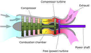
A free-turbine turboshaft is a form of turboshaft or turboprop gas turbine engine where the power is extracted from the exhaust stream of a gas turbine by an independent turbine, downstream of the gas turbine. The power turbine is not mechanically connected to the turbines that drive the compressors, hence the term "free", referring to the independence of the power output shaft. This is opposed to the power being extracted from the turbine/compressor shaft via a gearbox.

References

Notes

  1. "Internal Combustion Engine and Method" (PDF). United States Patent Office. March 26, 2002. Retrieved 2019-05-11.
  2. 1 2 3 Self 2008.
  3. "Rotary compressor and other engines" (PDF). Freepatentsonline.com. Retrieved 2011-12-06.
  4. "Rotary compressor and other engines".
  5. angellabsllc.com
  6. rotoblock.com
  7. roundengine.com
  8. "Toroidal engines". Greencarcongress.com. 2006-04-18. Retrieved 2011-12-06.
  9. "MYT Engine: US Patent "Internal Combustion Engine" #7415962 B2; Aug 26, 2008". Patft.uspto.gov. Archived from the original on 2016-01-14. Retrieved 2011-12-06.
  10. "Yomobil" (in Russian). Auto.lenta.ru.
  11. Rice, Vincent (22 September 2011). "The spherical genius of the Hüttlin Kugelmotor". Gizmag.com.
  12. "Cat-and-mouse engine".

Bibliography