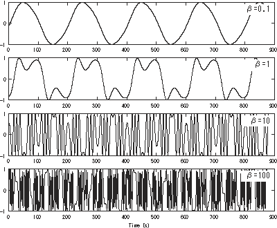
Frequency modulation synthesis

Last updated
FM synthesis using 2 operators
2op FM (large font).svg
A 220 Hz carrier tone fc modulated by a 440 Hz modulating tone fm, with various choices of frequency modulation index, β. The time domain signals are illustrated above, and the corresponding spectra are shown below (spectrum amplitudes in dB).
Waveforms for each β

Frequencymodulationdemo-td.png

Spectra for each β

Frequencymodulationdemo-fd.png

Frequency modulation synthesis (or FM synthesis) is a form of sound synthesis whereby the frequency of a waveform is changed by modulating its frequency with a modulator. The (instantaneous) frequency of an oscillator is altered in accordance with the amplitude of a modulating signal. [1]

Contents

FM synthesis can create both harmonic and inharmonic sounds. To synthesize harmonic sounds, the modulating signal must have a harmonic relationship to the original carrier signal. As the amount of frequency modulation increases, the sound grows progressively complex. Through the use of modulators with frequencies that are non-integer multiples of the carrier signal (i.e. inharmonic), inharmonic bell-like and percussive spectra can be created.

Applications

FM synthesis using analog oscillators may result in pitch instability. [2] However, FM synthesis can also be implemented digitally, which is more stable and became standard practice. Digital FM synthesis (equivalent to the phase modulation using the time integration of instantaneous frequency) was the basis of several musical instruments beginning as early as 1974. Yamaha built the first prototype digital synthesizer in 1974, based on FM synthesis, [3] before commercially releasing the Yamaha GS-1 in 1980. [4] The Synclavier I, manufactured by New England Digital Corporation beginning in 1978, included a digital FM synthesizer, using an FM synthesis algorithm licensed from Yamaha. [5] Yamaha's groundbreaking Yamaha DX7 synthesizer, released in 1983, brought FM to the forefront of synthesis in the mid-1980s. [6]

Amusement use: FM sound chips on PCs, arcades, game consoles, and mobile phones

FM synthesis also became the usual setting for games and software up until the mid-nineties. For IBM PC compatible systems, sound cards like the AdLib and Sound Blaster popularized Yamaha chips like the OPL2 and OPL3. Other computers such as the Sharp X68000 and MSX (Yamaha CX5M computer unit) use the OPM sound chip (which was also commonly used for arcade machines up to the mid-nineties), and the NEC PC-88 and PC-98 computers use the OPN and OPNA. For arcade systems and game consoles, OPNB was used as main basic sound generator board in Taito's arcade boards (with a variant of the OPNB being used in the Taito Z System) and notably used in SNK's Neo Geo arcade (MVS) and home console (AES) machines. The related OPN2 was used in the Sega's Mega Drive (Genesis) and Fujitsu's FM Towns Marty as one of its sound generator chips. Throughout the 2000s, FM synthesis was also used on a wide range of phones to play ringtones and other sounds, typically in the Yamaha SMAF format.

History

Don Buchla (mid-1960s)

Don Buchla implemented FM on his instruments in the mid-1960s, prior to Chowning's patent. His 158, 258 and 259 dual oscillator modules had a specific FM control voltage input, [7] and the model 208 (Music Easel) had a modulation oscillator hard-wired to allow FM as well as AM of the primary oscillator. [8] These early applications used analog oscillators, and this capability was also followed by other modular synthesizers and portable synthesizers including Minimoog and ARP Odyssey.

John Chowning (late-1960s–1970s)

Digital frequency modulation synthesis was developed by John Chowning Chowning.jpg
Digital frequency modulation synthesis was developed by John Chowning

By the mid-20th century, frequency modulation (FM), a means of carrying sound, had been understood for decades and was being used to broadcast radio transmissions. FM synthesis was developed since 1967 at Stanford University, California, by John Chowning, who was trying to create sounds different from analog synthesis [ citation needed ]. His algorithm[ citation needed ] was licensed to Japanese company Yamaha in 1973. [3] The implementation commercialized by Yamaha (US Patent 4018121 Apr 1977 [9] or U.S. Patent 4,018,121 [10] ) is actually based on phase modulation [ citation needed ], but the results end up being equivalent mathematically as both are essentially a special case of quadrature amplitude modulation [ citation needed ]. [11]

1970s–1980s

Expansions by Yamaha

Yamaha's engineers began adapting Chowning's algorithm for use in a commercial digital synthesizer, adding improvements such as the "key scaling" method to avoid the introduction of distortion that normally occurred in analog systems during frequency modulation [ citation needed ], though it would take several years before Yamaha released their FM digital synthesizers. [12] In the 1970s, Yamaha were granted a number of patents, under the company's former name "Nippon Gakki Seizo Kabushiki Kaisha", evolving Chowning's work. [10] Yamaha built the first prototype FM digital synthesizer in 1974. [3] Yamaha eventually commercialized FM synthesis technology with the Yamaha GS-1, the first FM digital synthesizer, released in 1980. [4]

FM digital synthesizer Yamaha DX7 (1983) YAMAHA DX7.jpg
FM digital synthesizer Yamaha DX7 (1983)

FM synthesis was the basis of some of the early generations of digital synthesizers, most notably those from Yamaha, as well as New England Digital Corporation under license from Yamaha. [5] Yamaha's DX7 synthesizer, released in 1983, was ubiquitous throughout the 1980s. Several other models by Yamaha provided variations and evolutions of FM synthesis during that decade. [13]

Yamaha had patented its hardware implementation of FM in the 1970s, [10] allowing it to nearly monopolize the market for FM technology until the mid-1990s.

Casio developed a related form of synthesis called phase distortion synthesis, used in its CZ range of synthesizers. It had a similar (but slightly differently derived) sound quality to the DX series.

1990s

Popularization after the expiration of patent

With the expiration of the Stanford University FM patent in 1995, digital FM synthesis can now be implemented freely by other manufacturers. The FM synthesis patent brought Stanford $20 million before it expired, making it (in 1994) "the second most lucrative licensing agreement in Stanford's history". [14] FM today is mostly found in software-based synths such as FM8 by Native Instruments or Sytrus by Image-Line, but it has also been incorporated into the synthesis repertoire of some modern digital synthesizers, usually coexisting as an option alongside other methods of synthesis such as subtractive, sample-based synthesis, additive synthesis, and other techniques. The degree of complexity of the FM in such hardware synths may vary from simple 2-operator FM, to the highly flexible 6-operator engines of the Korg Kronos and Alesis Fusion, to creation of FM in extensively modular engines such as those in the latest synthesisers by Kurzweil Music Systems.[ citation needed ]

Realtime Convolution & Modulation (AFM + Sample) and Formant Shaping Synthesis

New hardware synths specifically marketed for their FM capabilities disappeared from the market after the release of the Yamaha SY99 [15] and FS1R, [16] and even those marketed their highly powerful FM abilities as counterparts to sample-based synthesis and formant synthesis respectively. However, well-developed FM synthesis options are a feature of Nord Lead synths manufactured by Clavia, the Alesis Fusion range, the Korg Oasys and Kronos and the Modor NF-1. Various other synthesizers offer limited FM abilities to supplement their main engines.[ citation needed ]

Combining sets of 8 FM operators with multi-spectral wave forms began in 1999 by Yamaha in the FS1R. The FS1R had 16 operators, 8 standard FM operators and 8 additional operators that used a noise source rather than an oscillator as its sound source. By adding in tuneable noise sources the FS1R could model the sounds produced in the human voice and in a wind instrument, along with making percussion instrument sounds. The FS1R also contained an additional wave form called the Formant wave form. Formants can be used to model resonating body instrument sounds like the cello, violin, acoustic guitar, bassoon, English horn, or human voice. Formants can even be found in the harmonic spectrum of several brass instruments. [17]

2000s–present

Variable Phase Modulation, FM-X Synthesis, Altered FM, etc

In 2016, Korg released the Korg Volca FM, a, 3-voice, 6 operators FM iteration of the Korg Volca series of compact, affordable desktop modules, [18] . More recently Korg released the opsix (2020) and opsix SE (2023) integrating 6 operators FM synthesis with subtractive, analogue modeling, additive, semi-modular and Waveshaping. Yamaha released the Montage, which combines a 128-voice sample-based engine with a 128-voice FM engine. This iteration of FM is called FM-X, and features 8 operators; each operator has a choice of several basic wave forms, but each wave form has several parameters to adjust its spectrum. [19] The Yamaha Montage was followed by the more affordable Yamaha MODX in 2018, with 64-voice, 8 operators FM-X architecture in addition to a 128-voice sample-based engine. [20] Elektron in 2018 launched the Digitone, an 8-voice, 4 operators FM synth featuring Elektron's renowned sequence engine. [21]

FM-X synthesis was introduced with the Yamaha Montage synthesizers in 2016. FM-X uses 8 operators. Each FM-X operator has a set of multi-spectral wave forms to choose from, which means each FM-X operator can be equivalent to a stack of 3 or 4 DX7 FM operators. The list of selectable wave forms includes sine waves, the All1 and All2 wave forms, the Odd1 and Odd2 wave forms, and the Res1 and Res2 wave forms. The sine wave selection works the same as the DX7 wave forms. The All1 and All2 wave forms are a saw-tooth wave form. The Odd1 and Odd2 wave forms are pulse or square waves. These two types of wave forms can be used to model the basic harmonic peaks in the bottom of the harmonic spectrum of most instruments. The Res1 and Res2 wave forms move the spectral peak to a specific harmonic and can be used to model either triangular or rounded groups of harmonics further up in the spectrum of an instrument. Combining an All1 or Odd1 wave form with multiple Res1 (or Res2) wave forms (and adjusting their amplitudes) can model the harmonic spectrum of an instrument or sound. [17] [ citation needed ]

Spectral analysis

2-operator demonstation: if the frequency of the modulator is lower than that of the carrier, the output note will be that of the modulator.

There are multiple variations of FM synthesis, including:

etc.

As the basic of these variations, we analyze the spectrum of 2 operators (linear FM synthesis using two sinusoidal operators) on the following.

2 operators

The spectrum generated by FM synthesis with one modulator is expressed as follows: [22] [23]

For modulation signal , the carrier signal is: [note 1]

If we were to ignore the constant phase terms on the carrier and the modulator , finally we would get the following expression, as seen on Chowning 1973 and Roads 1996 , p.  232:

where are angular frequencies () of carrier and modulator, is frequency modulation index, and amplitudes is -th Bessel function of first kind, respectively. [note 2]

See also

Related Research Articles

Phase modulation (PM) is a modulation pattern for conditioning communication signals for transmission. It encodes a message signal as variations in the instantaneous phase of a carrier wave. Phase modulation is one of the two principal forms of angle modulation, together with frequency modulation.

A Costas loop is a phase-locked loop (PLL) based circuit which is used for carrier frequency recovery from suppressed-carrier modulation signals and phase modulation signals. It was invented by John P. Costas at General Electric in the 1950s. Its invention was described as having had "a profound effect on modern digital communications". The primary application of Costas loops is in wireless receivers. Its advantage over other PLL-based detectors is that at small deviations the Costas loop error voltage is as compared to . This translates to double the sensitivity and also makes the Costas loop uniquely suited for tracking Doppler-shifted carriers, especially in OFDM and GPS receivers.

Double-sideband suppressed-carrier transmission (DSB-SC) is transmission in which frequencies produced by amplitude modulation (AM) are symmetrically spaced above and below the carrier frequency and the carrier level is reduced to the lowest practical level, ideally being completely suppressed.

<span class="mw-page-title-main">Phase-locked loop</span> Electronic control system

A phase-locked loop or phase lock loop (PLL) is a control system that generates an output signal whose phase is related to the phase of an input signal. There are several different types; the simplest is an electronic circuit consisting of a variable frequency oscillator and a phase detector in a feedback loop. The oscillator's frequency and phase are controlled proportionally by an applied voltage, hence the term voltage-controlled oscillator (VCO). The oscillator generates a periodic signal of a specific frequency, and the phase detector compares the phase of that signal with the phase of the input periodic signal, to adjust the oscillator to keep the phases matched.

The propagation constant of a sinusoidal electromagnetic wave is a measure of the change undergone by the amplitude and phase of the wave as it propagates in a given direction. The quantity being measured can be the voltage, the current in a circuit, or a field vector such as electric field strength or flux density. The propagation constant itself measures the dimensionless change in magnitude or phase per unit length. In the context of two-port networks and their cascades, propagation constant measures the change undergone by the source quantity as it propagates from one port to the next.

<span class="mw-page-title-main">Bremsstrahlung</span> Electromagnetic radiation due to deceleration of charged particles

In particle physics, bremsstrahlung is electromagnetic radiation produced by the deceleration of a charged particle when deflected by another charged particle, typically an electron by an atomic nucleus. The moving particle loses kinetic energy, which is converted into radiation, thus satisfying the law of conservation of energy. The term is also used to refer to the process of producing the radiation. Bremsstrahlung has a continuous spectrum, which becomes more intense and whose peak intensity shifts toward higher frequencies as the change of the energy of the decelerated particles increases.

In physics, specifically in quantum mechanics, a coherent state is the specific quantum state of the quantum harmonic oscillator, often described as a state that has dynamics most closely resembling the oscillatory behavior of a classical harmonic oscillator. It was the first example of quantum dynamics when Erwin Schrödinger derived it in 1926, while searching for solutions of the Schrödinger equation that satisfy the correspondence principle. The quantum harmonic oscillator arise in the quantum theory of a wide range of physical systems. For instance, a coherent state describes the oscillating motion of a particle confined in a quadratic potential well. The coherent state describes a state in a system for which the ground-state wavepacket is displaced from the origin of the system. This state can be related to classical solutions by a particle oscillating with an amplitude equivalent to the displacement.

Chebyshev filters are analog or digital filters that have a steeper roll-off than Butterworth filters, and have either passband ripple or stopband ripple. Chebyshev filters have the property that they minimize the error between the idealized and the actual filter characteristic over the operating frequency range of the filter, but they achieve this with ripples in the passband. This type of filter is named after Pafnuty Chebyshev because its mathematical characteristics are derived from Chebyshev polynomials. Type I Chebyshev filters are usually referred to as "Chebyshev filters", while type II filters are usually called "inverse Chebyshev filters". Because of the passband ripple inherent in Chebyshev filters, filters with a smoother response in the passband but a more irregular response in the stopband are preferred for certain applications.

In physics, a wave vector is a vector used in describing a wave, with a typical unit being cycle per metre. It has a magnitude and direction. Its magnitude is the wavenumber of the wave, and its direction is perpendicular to the wavefront. In isotropic media, this is also the direction of wave propagation.

In rotordynamics, the rigid rotor is a mechanical model of rotating systems. An arbitrary rigid rotor is a 3-dimensional rigid object, such as a top. To orient such an object in space requires three angles, known as Euler angles. A special rigid rotor is the linear rotor requiring only two angles to describe, for example of a diatomic molecule. More general molecules are 3-dimensional, such as water, ammonia, or methane.

<span class="mw-page-title-main">Phasor</span> Complex number representing a particular sine wave

In physics and engineering, a phasor is a complex number representing a sinusoidal function whose amplitude, and initial phase are time-invariant and whose angular frequency is fixed. It is related to a more general concept called analytic representation, which decomposes a sinusoid into the product of a complex constant and a factor depending on time and frequency. The complex constant, which depends on amplitude and phase, is known as a phasor, or complex amplitude, and sinor or even complexor.

In signal processing, linear phase is a property of a filter where the phase response of the filter is a linear function of frequency. The result is that all frequency components of the input signal are shifted in time by the same constant amount, which is referred to as the group delay. Consequently, there is no phase distortion due to the time delay of frequencies relative to one another.

The Havriliak–Negami relaxation is an empirical modification of the Debye relaxation model in electromagnetism. Unlike the Debye model, the Havriliak–Negami relaxation accounts for the asymmetry and broadness of the dielectric dispersion curve. The model was first used to describe the dielectric relaxation of some polymers, by adding two exponential parameters to the Debye equation:

<span class="mw-page-title-main">Acousto-optics</span> The study of sound and light interaction

Acousto-optics is a branch of physics that studies the interactions between sound waves and light waves, especially the diffraction of laser light by ultrasound through an ultrasonic grating.

<span class="mw-page-title-main">Biarc</span>

A biarc is a smooth curve formed from two circular arcs. In order to make the biarc smooth, the two arcs should have the same tangent at the connecting point where they meet.

A vacuum Rabi oscillation is a damped oscillation of an initially excited atom coupled to an electromagnetic resonator or cavity in which the atom alternately emits photon(s) into a single-mode electromagnetic cavity and reabsorbs them. The atom interacts with a single-mode field confined to a limited volume V in an optical cavity. Spontaneous emission is a consequence of coupling between the atom and the vacuum fluctuations of the cavity field.

The Kapitza–Dirac effect is a quantum mechanical effect consisting of the diffraction of matter by a standing wave of light. The effect was first predicted as the diffraction of electrons from a standing wave of light by Paul Dirac and Pyotr Kapitsa in 1933. The effect relies on the wave–particle duality of matter as stated by the de Broglie hypothesis in 1924.

<span class="mw-page-title-main">Optical phase space</span> Phase space used in quantum optics

In quantum optics, an optical phase space is a phase space in which all quantum states of an optical system are described. Each point in the optical phase space corresponds to a unique state of an optical system. For any such system, a plot of the quadratures against each other, possibly as functions of time, is called a phase diagram. If the quadratures are functions of time then the optical phase diagram can show the evolution of a quantum optical system with time.

Differential phase is a kind of linearity distortion which affects the color hue in TV broadcasting.

<span class="mw-page-title-main">Trochoidal wave</span> Exact solution of the Euler equations for periodic surface gravity waves

In fluid dynamics, a trochoidal wave or Gerstner wave is an exact solution of the Euler equations for periodic surface gravity waves. It describes a progressive wave of permanent form on the surface of an incompressible fluid of infinite depth. The free surface of this wave solution is an inverted (upside-down) trochoid – with sharper crests and flat troughs. This wave solution was discovered by Gerstner in 1802, and rediscovered independently by Rankine in 1863.

References

Footnotes

  1. Note that modulation signal as instantaneous frequency is converted to the phase of carrier signal , by time integral between .
  2. The above expression is transformed using trigonometric addition formulas
    and a lemma of Bessel function
    (Source: Kreh 2012)
    as following:

Citations

  1. Dodge & Jerse 1997 , p. 115
  2. McGuire, Sam; Matějů, Zbyněk (2020-12-28). The Art of Digital Orchestration. CRC Press. ISBN   978-1-000-28699-1.
  3. 1 2 3 "[Chapter 2] FM Tone Generators and the Dawn of Home Music Production". Yamaha Synth 40th Anniversary - History. Yamaha Corporation. 2014. Archived from the original on 2017-05-11.
  4. 1 2 Curtis Roads (1996). The computer music tutorial. MIT Press. p. 226. ISBN   0-262-68082-3 . Retrieved 2011-06-05.
  5. 1 2 "1978 New England Digital Synclavier". Mix. Penton Media. September 1, 2006.
  6. "The top 10 classic synth presets (and where you can hear them)". MusicRadar . Retrieved October 19, 2018.
  7. Dr. Hubert Howe (1960s). Buchla Electronic Music System: Users Manual written for CBS Musical Instruments (Buchla 100 Owner's Manual). Educational Research Department, CBS Musical Instruments, Columbia Broadcasting System. p.  7. At this point we may consider various additional signal modifications that we may wish to make to the series of tones produced by the above example. For instance, if we would like to add frequency modulation to the tones, it is necessary to patch another audio signal into the jack connected by a line to the middle dial on the Model 158 Dual Sine-Sawtooth Oscillator. ...
  8. Atten Strange (1974). Programming and Metaprogramming in the Electro-Organism - An Operating Directive for the Music Easel. Buchla and Associates.
  9. "U.S. Patent 4018121 Apr 1977". patft.uspto.gov. Retrieved 2017-04-30.
  10. 1 2 3 "Patent US4018121 - Method of synthesizing a musical sound - Google Patents" . Retrieved 2017-04-30.
  11. Rob Hordijk. "FM synthesis on Modular". Nord Modular & Micro Modular V3.03 tips & tricks. Clavia DMI AB. Archived from the original on 2007-04-07. Retrieved 2013-03-23.
  12. Holmes, Thom (2008). "Early Computer Music". Electronic and experimental music: technology, music, and culture (3rd ed.). Taylor & Francis. pp. 257–8. ISBN   978-0-415-95781-6 . Retrieved 2011-06-04.
  13. Gordon Reid (September 2001). "Sounds of the '80s Part 2: The Yamaha DX1 & Its Successors (Retro)". Sound on Sound. Archived from the original on 17 September 2011. Retrieved 2011-06-29.
  14. Stanford University News Service (06/07/94), Music synthesis approaches sound quality of real instruments
  15. "Yamaha SY99 spec". Yamaha Corporation (in Japanese).
  16. Poyser, Debbie; Johnson, Derek (1998). "Yamaha FS1R - FM Synthesis / Formant-shaping Tone Generator". Sound on Sound . No. December 1998.
  17. 1 2 Zollinger, W. Thor (Dec 2017). "FM_Synthesis_of_Real_Instruments" (PDF). Archived (PDF) from the original on 2017-09-25.
  18. Volca FM product page
  19. Yamaha Montage Product Features Page
  20. Yamaha MODX Product Features Page
  21. Digitone product page
  22. Chowning 1973 , pp. 1–2
  23. Doering, Ed. "Frequency Modulation Mathematics" . Retrieved 2013-04-11.

Bibliography