Harmonic drive

Last updated

Harmonic Drive is the brand name of strain wave gear trademarked by the Harmonic Drive company, and invented in 1957 by C.W. Musser.

Contents

Harmonic Drive SE strain wave gear set consisting of wave generator bearing (top left), flexspline cup (top right) and circular spline ring (bottom). Harmonic Drive AG strain wave gear set.jpg
Harmonic Drive SE strain wave gear set consisting of wave generator bearing (top left), flexspline cup (top right) and circular spline ring (bottom).

It is very commonly implemented in robotics today [1] and used in aerospace as well, [2] for gear reduction but may also be used to increase rotational speed, or for differential gearing.

History

The basic concept of strain wave gearing (SWG) was introduced by C.W. Musser in his 1957 patent. [3] It was first used successfully in 1960 by USM Co. and later by Hasegawa Gear Works, Ltd. under license of USM. Later, Hasegawa Gear Works, Ltd. became Harmonic Drive Systems Inc. located in Japan and USM Co. Harmonic Drive division became Harmonic Drive Technologies Inc. [4] [5]

The electrically driven wheels of the Apollo Lunar Rover included strain wave gears in their gearing. Also, the winches used on Skylab to deploy the solar panels were powered using strain wave gears. Both of these system were developed by The Harmonic Drive Division of United Shoe Machinery Corp.[ citation needed ]

On January 1, 2006, Harmonic Drive Technologies/Nabtesco of Peabody, MA and HD Systems of Hauppauge, NY, merged to form a new joint venture, Harmonic Drive LLC. [6] HD Systems, Inc. was a subsidiary company of Harmonic Drive System, Inc. Offices are maintained in Peabody, MA, Hauppauge, NY, San Jose, CA and Oak Park, IL. Harmonic Drive Systems, Inc., Japan is headquartered in Tokyo with its primary manufacturing location in Hotaka, Japan. Harmonic Drive SE has its European headquarters and manufacturing in Limburg/Lahn,Germany.

Mechanics

Cross section of a harmonic gear.
input shaft
wave generator
flexspline
circular spline
output shaft
housing Harmonic drive cross Legend.svg
Cross section of a harmonic gear.
  1. input shaft
  2. wave generator
  3. flexspline
  4. circular spline
  5. output shaft
  6. housing
Blue (outer circle): circular spline (fixed)
Red (middle flexible circle): flex spline (attached to output shaft, which is not shown)
Green (inner oval): wave generator (attached to input shaft; inner ball bearing and shaft are not shown) HarmonicDriveAni.gif
Blue (outer circle): circular spline (fixed)
Red (middle flexible circle): flex spline (attached to output shaft, which is not shown)
Green (inner oval): wave generator (attached to input shaft; inner ball bearing and shaft are not shown)

The strain wave gearing theory is based on elastic dynamics and utilizes the flexibility of metal. The mechanism has three basic components: a wave generator (2 / green), a flex spline (3 / red), and a circular spline (4 / blue). More complex versions have a fourth component normally used to shorten the overall length or to increase the gear reduction within a smaller diameter, but still follow the same basic principles.

The wave generator is made up of two separate parts: an elliptical disk called a wave generator plug and an outer ball bearing. The gear plug is inserted into the bearing, giving the bearing an elliptical shape as well.

The flex spline is shaped like a shallow cup. The sides of the spline are very thin, but the bottom is relatively rigid. This results in significant flexibility of the walls at the open end due to the thin wall, and in the closed side being quite rigid and able to be tightly secured (to a shaft, for example). Teeth are positioned radially around the outside of the flex spline. The flex spline fits tightly over the wave generator, so that when the wave generator plug is rotated, the flex spline deforms to the shape of a rotating ellipse and does not slip over the outer elliptical ring of the ball bearing. The ball bearing lets the flex spline rotate independently to the wave generator's shaft.

The circular spline is a rigid circular ring with teeth on the inside. The flex spline and wave generator are placed inside the circular spline, meshing the teeth of the flex spline and the circular spline. Because the flex spline is deformed into an elliptical shape, its teeth only actually mesh with the teeth of the circular spline in two regions on opposite sides of the flex spline (located on the major axis of the ellipse).

Assume that the wave generator is the input rotation. As the wave generator plug rotates, the flex spline teeth which are meshed with those of the circular spline slowly change position. The major axis of the flex spline's ellipse rotates with wave generator, so the points where the teeth mesh revolve around the center point at the same rate as the wave generator's shaft. The key to the design of the strain wave gear is that there are fewer teeth (often for example two fewer) on the flex spline than there are on the circular spline. This means that for every full rotation of the wave generator, the flex spline would be required to rotate a slight amount (two teeth in this example) backward relative to the circular spline. Thus the rotation action of the wave generator results in a much slower rotation of the flex spline in the opposite direction.

For a strain wave gearing mechanism, the gearing reduction ratio can be calculated from the number of teeth on each gear:

For example, if there are 202 teeth on the circular spline and 200 on the flex spline, the reduction ratio is (200  202)/200 = 0.01

Thus the flex spline spins at 1/100 the speed of the wave generator plug and in the opposite direction. Different reduction ratios are set by changing the number of teeth. This can either be achieved by changing the mechanism's diameter or by changing the size of the individual teeth and thereby preserving its size and weight. The range of possible gear ratios is limited by tooth size limits for a given configuration.

Advantages

The advantages include: no backlash, high compactness and light weight, high gear ratios, reconfigurable ratios within a standard housing, good resolution and excellent repeatability (linear representation) when repositioning inertial loads, [7] high torque capability, and coaxial input and output shafts. [6] High gear reduction ratios are possible in a small volume (a ratio from 30:1 up to 320:1 is possible in the same space in which planetary gears typically only produce a 10:1 ratio).

See also

Related Research Articles

Coupling construction detail used to connect two shafts (that can but do not have to be misaligned or moving or similar) together at their ends for the purpose of transmitting power

A coupling is a device used to connect two shafts together at their ends for the purpose of transmitting power. The primary purpose of couplings is to join two pieces of rotating equipment while permitting some degree of misalignment or end movement or both. In a more general context, a coupling can also be a mechanical device that serves to connect the ends of adjacent parts or objects. Couplings do not normally allow disconnection of shafts during operation, however there are torque limiting couplings which can slip or disconnect when some torque limit is exceeded. Selection, installation and maintenance of couplings can lead to reduced maintenance time and maintenance cost.

Gear rotating wheel having teeth which mesh with another cogwheel or toothed part, used to transmit torque, convert rotation to translation or rarely other purposes

A gear or cogwheel is a rotating machine part having cut teeth or, in the case of a cogwheel, inserted teeth, which mesh with another toothed part to transmit torque. Geared devices can change the speed, torque, and direction of a power source. Gears almost always produce a change in torque, creating a mechanical advantage, through their gear ratio, and thus may be considered a simple machine. The teeth on the two meshing gears all have the same shape. Two or more meshing gears, working in a sequence, are called a gear train or a transmission. A gear can mesh with a linear toothed part, called a rack, producing translation instead of rotation.

Starter (engine) electric motor used to start an internal combustion engine

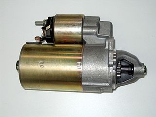
A starter is a device used to rotate (crank) an internal-combustion engine so as to initiate the engine's operation under its own power. Starters can be electric, pneumatic, or hydraulic. In the case of very large engines, the starter can even be another internal-combustion engine.

Differential (mechanical device) type of simple planetary gear train

A differential is a gear train with three shafts that has the property that the rotational speed of one shaft is the average of the speeds of the others, or a fixed multiple of that average.

Rack and pinion machine element

A rack and pinion is a type of linear actuator that comprises a circular gear engaging a linear gear, which operate to translate rotational motion into linear motion. Driving the pinion into rotation causes the rack to be driven linearly. Driving the rack linearly will cause the pinion to be driven into a rotation. A rack and pinion drive can use both straight and helical gears. Helical gears are preferred due to their quieter operation and higher load bearing capacity. The maximum force that can be transmitted in a rack and pinion mechanism is determined by the tooth pitch and the size of the pinion.

Hobbing

Hobbing is a machining process for gear cutting, cutting splines, and cutting sprockets on a hobbing machine, which is a special type of milling machine. The teeth or splines of the gear are progressively cut into the material by a series of cuts made by a cutting tool called a hob. Compared to other gear forming processes it is relatively inexpensive but still quite accurate, thus it is used for a broad range of parts and quantities.

Epicyclic gearing consists of two gears mounted so that the center of one gear revolves around the center of the other

An epicyclic gear train consists of two gears mounted so that the center of one gear revolves around the center of the other. A carrier connects the centers of the two gears and rotates to carry one gear, called the planet gear or planet pinion, around the other, called the sun gear or sun wheel. The planet and sun gears mesh so that their pitch circles roll without slip. A point on the pitch circle of the planet gear traces an epicycloid curve. In this simplified case, the sun gear is fixed and the planetary gear(s) roll around the sun gear.

Transmission (mechanics) machine in a power transmission system for controlled application of the power;gearbox,uses gears/gear trains to provide speed,torque conversions from a rotating power source to another device;reduces the higher engine speed to the slower wheel speed

A transmission is a machine in a power transmission system, which provides controlled application of the power. Often the term 5 speed transmission refers simply to the gearbox that uses gears and gear trains to provide speed and torque conversions from a rotating power source to another device.

Manual transmission Type of transmission used in motor vehicle applications

A manual transmission, also known as a manual gearbox, a standard transmission, stick shift, or simply gearbox, is a type of transmission used in motor vehicle applications. It uses a driver-operated clutch, usually engaged and disengaged by a foot pedal or hand lever, for regulating torque transfer from the engine to the transmission; and a gear selector that can be operated by hand.

Yaw drive

The yaw drive is an important component of the horizontal axis wind turbines' yaw system. To ensure the wind turbine is producing the maximal amount of electric energy at all times, the yaw drive is used to keep the rotor facing into the wind as the wind direction changes. This only applies for wind turbines with a horizontal axis rotor. The wind turbine is said to have a yaw error if the rotor is not aligned to the wind. A yaw error implies that a lower share of the energy in the wind will be running through the rotor area..

Gear train Mechanical transmission using multiple gears.

A gear train is a mechanical system formed by mounting gears on a frame so the teeth of the gears engage.

Cycloidal drive

A cycloidal drive or cycloidal speed reducer is a mechanism for reducing the speed of an input shaft by a certain ratio. Cycloidal speed reducers are capable of relatively high ratios in compact sizes with very low backlash.

Bevel gear

Bevel gears are gears where the axes of the two shafts intersect and the tooth-bearing faces of the gears themselves are conically shaped. Bevel gears are most often mounted on shafts that are 90 degrees apart, but can be designed to work at other angles as well. The pitch surface of bevel gears is a cone.

Backlash (engineering) clearance between mating components

In mechanical engineering, backlash, sometimes called lash or play, is a clearance or lost motion in a mechanism caused by gaps between the parts. It can be defined as "the maximum distance or angle through which any part of a mechanical system may be moved in one direction without applying appreciable force or motion to the next part in mechanical sequence".p. 1-8 An example, in the context of gears and gear trains, is the amount of clearance between mated gear teeth. It can be seen when the direction of movement is reversed and the slack or lost motion is taken up before the reversal of motion is complete. It can be heard from the railway couplings when a train reverses direction. Another example is in a valve train with mechanical tappets, where a certain range of lash is necessary for the valves to work properly.

Hirth joint

A Hirth joint or Hirth coupling is a type of mechanical connection named after its developer Albert Hirth. It is used to connect two pieces of a shaft together and is characterized by tapered teeth that mesh together on the end faces of each half shaft.

Splines are ridges or teeth on a drive shaft that mesh with grooves in a mating piece and transfer torque to it, maintaining the angular correspondence between them.

In horology, a wheel train is the gear train of a mechanical watch or clock. Although the term is used for other types of gear trains, the long history of mechanical timepieces has created a traditional terminology for their gear trains which is not used in other applications of gears.

Mechanism (engineering) device designed to transform input forces and movement into a desired set of output forces and movement

In engineering, a mechanism is a device that transforms input forces and movement into a desired set of output forces and movement. Mechanisms generally consist of moving components that can include:

Barring engine

A barring engine is a small engine, usually a steam engine, that forms part of the installation of a large stationary steam engine. It is used to turn the main engine to a favourable position from which it can be started. If the main engine has stopped close to its dead centre it is unable to restart itself.

Strain wave gearing also known as harmonic gearing is a special type of mechanical gear system that can improve certain characteristics compared to traditional gearing systems such as helical gears or planetary gears. It was invented in 1957 by C.W. Musser while he was a research advisor at United Shoe Machinery (USM). The advantages include: no backlash, compactness and light weight, high gear ratios, reconfigurable ratios within a standard housing, good resolution and excellent repeatability when repositioning inertial loads, high torque capability, and coaxial input and output shafts. High gear reduction ratios are possible in a small volume . Disadvantages include a tendency for 'wind-up' in the low torque region. Strain wave gears are typically used in industrial motion control, machine tool, printing machine, robotics and aerospace, for gear reduction but may also be used to increase rotational speed, or for differential gearing.

References

  1. Li, Z; Melek, WW; Clark, C (2009). "Decentralized robust control of robot manipulators with harmonic drive transmission and application to modular and reconfigurable serial arms". Robotica. 27 (2): 291–302. doi:10.1017/S0263574708004712.
  2. Ueura, K; Kiyosawa, Y; Kurogi, J; Kanai, S; Miyaba, H; Maniwa, K; Suzuki, M; Obara, S (2008). "Tribological aspects of a strain wave gearing system with specific reference to its space application". Proceedings of the Institution of Mechanical Engineers, Part J: Journal of Engineering Tribology. 222 (8): 1051–1061. doi:10.1243/13506501JET415. ISSN   1350-6501.
  3. U.S. Patent 2,906,143
  4. "Harmonic drive companies merge", Motion System Design, 2006.
  5. Harmonic Drive Systems Company Information
  6. 1 2 Lauletta, Anthony (April 2006). "The Basics of Harmonic Drive Gearing" (PDF). Gear Product News. pp. 32–36.
  7. Chironis, Nicholas; Sclater, Neil (2007). Mechanisms and Mechanical Devices Sourcebook. ISBN   0-07-146761-0.