Modifications to slopes to reduce the effect of landslides
This article needs additional or more specific categories. Please help out by adding categories to it so that it can be listed with similar articles.(April 2025)
Landslide mitigation refers to human construction activities on slopes undertaken with the goal of lessening the effect of landslides. Landslides can be triggered by many, sometimes concomitant causes. In addition to shallow erosion or reduction of shear strength caused by seasonal rainfall, landslides may be triggered by anthropic activities, such as adding excessive weight above the slope or digging at either the mid-slope or foot of the slope.
Often, individual phenomena join to generate instability over time, which often does not allow a reconstruction of the evolution of a particular landslide. Therefore, landslide hazard mitigation measures are not generally classified according to the phenomenon that might cause a landslide.[1] Instead, they are classified by the sort of slope stabilization method used:
Geometric methods, in which the geometry of the hillside is changed (in general the slope);
Hydrogeological methods, in which an attempt is made to lower the groundwater level or to reduce the water content of the material
Chemical and mechanical methods, in which attempts are made to increase the shear strength of the unstable mass or to introduce active external forces (e.g. anchors, rock or ground nailing) or passive (e.g. structural wells, piles or reinforced ground) to counteract the destabilizing forces.
Each of these methods varies somewhat with the type of material that makes up the slope.
Rock slopes
Reinforcement measures
Anchor structure.
Reinforcement measures generally introduce metal elements, which increase the shear strength of the rock and reduce the stress release created when the rock is cut. Reinforcement measures are made up of metal rock nails or anchors. Anchorage subjected to pretensioning is classified as active anchorage. Passive anchorage is not subjected to pretensioning and can be used both to nail single unstable blocks and to reinforce large portions of rock.[1]
Anchorage can also be used for pre-reinforcement on a scarp to limit hillside decompression associated with cutting. Parts of an anchorage include:
the header: the set of elements (anchor plate, blocking device, etc.) that transmit the traction strength of the anchor to the anchored structure or to the rock
the reinforcement: part of the anchor, concreted and otherwise, placed under traction; can be constituted by a metal rod, a metal cable, a strand, etc.
the length of the foundation: the deepest portion of the anchor, fixed to the rock with chemical bonds or mechanical devices, which transfer the load to the rock itself
the free length: the non-concreted length.
Positioning of anchors and nails in an unstable rocky hillside.
When the anchorage acts over a short length it is defined as a bolt, which is not structurally connected to the free length, made up of an element resistant to traction (normally a steel bar of less than 12 m protected against corrosion by a concrete sheath).
The anchorage device may be connected to the ground by chemical means, mechanical expansion or concreting. In the first case, polyester resin cartridges are placed in a perforation to fill the ring space around the end part of the bolt. The main advantage of this type of anchorage lies in its simplicity and in the speed of installation.[1] The main disadvantage is in its limited strength.[citation needed]
In the second case, the anchorage is composed of steel wedges driven into the sides of the hole. The advantage of this type of anchorage lies in the speed of installation and in the fact that the tensioning can be achieved immediately.[citation needed] The main disadvantage with this type of anchorage is that it can only be used with hard rock, and the maximum traction force is limited.[citation needed]
In the third case, the anchorage is achieved by concreting the whole metal bar. This is the most-used method since the materials are cheap and installation is simple.[citation needed]
Injected concrete mixes can be used in many different rocks and grounds, and the concrete sheath protects the bar from corrosion. The concrete mixture is generally made up of water and cement in the ratio W/C = 0.40-0.45, producing a sufficiently fluid mixture to allow pumping into the hole, while at the same time, providing high mechanical strength when set.[1]
As far as the working mechanism of a rock nail is concerned, the strains of the rock induce a stress state in the nail composed of shear and traction stress, due to the roughness of the joints, to their opening and to the direction of the nail, generally non-orthogonal to the joint itself. The execution phases of setting up the nail provides for:
formation of any header niche and perforation
setting up of a reinforcement bar (e.g. a 4–6 m long FeB44k bar)
concrete injection of the bar
sealing of the header or of the top part of the hole
Closing up and cementing any cracks in the rock can prevent pressure caused by water during the freeze-thaw cycles from producing progressive breaking in the reinforcement system set up. The procedure for this usually consists of:
cleaning out and washing of the cracks;
plastering of the crack;
predisposition of the injection tubes at suitable inter-axes, parallel to the crack, through which the concrete mix is injected;
sequential injection of the mixture from bottom to top and at low pressure (1-3 atm.) until refusal or until no flow back of the mixture is noted from the tubes placed higher up.
The injection mixtures have approximately the following composition:
cement 10kg;
water 65 l
fluidity and anti-shrinkage additive or bentonite 1-5 kg.
The presence of water within a rocky hillside is one of the major factors leading to instability. Knowledge of the water pressure and of the runoff mode is important to stability analysis, and to planning measures to improve hillside stability.
Hoek and Bray (1981) provide a scheme of possible measures to reduce not only the amount of water, which is itself negligible as a cause of instability, but also the pressure applied by the water.[1]
The proposed scheme was elaborated taking three principles into account:
Preventing water entering the hillside through open or discontinuity traction cracks
Reducing water pressure in the vicinity of potential breakage surfaces through selective shallow and sub-shallow drainage.
Placing drainage in order to reduce water pressure in the immediate vicinity of the hillside.
The measures that reduce the effects of water can be shallow or deep. Shallow drainage work mainly intercepts surface runoff and keeps it away from potentially unstable areas. In reality, on rocky hillsides this type of measure alone is usually insufficient to stabilise a hillside.[citation needed] Deep drainage is the most effective.[citation needed] Sub horizontal drainage is very effective in reducing pore-pressure along crack surfaces or potential breakage surfaces. In rocks, the choice of drain spacing, slope, and length is dependent on the hillside geometry and, more importantly, the structural formation of the mass. Features such as position, spacing and discontinuity opening persistence condition, apart from the mechanical characteristics of the rock, the water runoff mode inside the mass. Therefore, only by intercepting the mostly drained discontinuities can there be an efficient result. Sub horizontal drains are accompanied by surficial collectors which gather the water and take it away through networks of small surface channels.
Vertical drainage is generally associated with sunken pumps, which have the task of draining the water and lowering the groundwater level. As continuous cycle pumps can have high running costs, the use of this technique is commonly reserved for limited periods.[citation needed] Drainage galleries are rather different in terms of efficiency. They are considered to be the most efficient drainage system for rocks even if they have the drawback of requiring very high technological and financial investment.[citation needed]
When used in rocks, this technique can be highly efficient in lowering water pressure. Drainage galleries can be associated with a series of radial drains which augment their efficiency. The positioning of this type of work is certainly connected to the local morphological, geological and structural conditions.
Geometry modification
This type of measure is used in those cases in which the rock face is sound and stable below the material to be removed. Examples include unstable material at the top of the hillside, rock blocks thrusting out from the hillside profile, vegetation that can widen the rock joints, rock blocks isolated from the joints.
Detachment measures are carried out where there are risks due to infrastructure or the passage of people at the foot of the hillside. This type of measure can solve the problem by eliminating the hazard. However, it should be ensured that once the measure is carried out, the problem does not re-emerge in the short term. In fact, where there are very cracked rocks, the shallower rock portions can undergo mechanical incoherence, sometimes encouraged by extremes of climate, causing the isolation of unstable blocks.
The measure can be effected in various ways, which range from demolition with pick axes to the use of explosives. In the case of high and/or not easily accessible faces it is necessary to turn to specialists who work acrobatically.
When explosives are used, sometimes controlled demolition can minimise or nullify the undesired effects resulting from the explosion of the charges, safeguarding the integrity of the surrounding rock.
Controlled demolition is based on the drilling of holes placed at a short distance from each other and parallel to the scarp to be demolished. The diameter of the holes generally varies from 40 to 80mm; the spacing of the holes is generally about 10 to 12 times the diameter. The charge fuse times are established so that those at the outer edges explode first and the more internal ones successively, so that the area of the operation is delimited.
Protection measures
A boulder catching net on a trail at Multnomah Falls, Oregon, USA, erected to protect hikers from debris falling down the steep incline.
Protecting infrastructure and towns from rockfalls.
Identification of the cause of alteration or the possibility of rockfall allows mitigation measures to be tailored to individual sites. The most-used passive protection measures are boulder-gathering trenches at the foot of the hillside, metal containment nets, and boulder barriers.[3]
Boulder barriers are generally composed of suitably rigid metal nets. Various structural types are on the market, for which the manufacturers specify the kinetic energy of absorption based on an elemental analysis of the structure under projectile collision conditions.
Another type of boulder containment barrier is the earth embankment, sometimes reinforced with geo-synthetics (reinforced ground). The advantages of such earthworks over nets are: easier maintenance, higher absorption of kinetic energy, and lower environmental impacts.[citation needed]
Soil slopes
Geometric modification
The operation of re-profiling a slope with the aim of improving its stability, can be achieved by either:[citation needed]
Lowering the angle of the slope, or
Positioning infill at the foot of the slope
Slope angles can be reduced by digging out the brow of the slope, usually in a step-wise fashion. This method is effective for correcting shallow forms of instability, where movement is limited to layers of ground near the surface and when the slopes are higher than 5m. Steps created by this method may also reduce surface erosion. However, caution is necessary to avoid the onset of local breakage following the cuts.
In contrast, infill at the foot of the slope has a stabilising effect on a translational or deep rotational landslide, in which the landslide surface at the top submerges and describes a sub-vertical surface that re-emerges in the area at the foot of the slope. The process of infill at the foot of the slope may include construction of berms, gravitational structures such as gabions, or reinforced ground (i.e., concrete blocks).
The choice between reducing the slope or infilling at the foot is usually controlled by location-specific constraints at the top or at the foot of the slope. In cases of slope stabilisation where there are no constraints (usually natural slopes), a combination of slope reduction and infilling at the foot of the slope is adopted to avoid heavy work of just one type. In the case of natural slopes, the choice of re-profiling scheme is not as simple as that for artificial slopes. The natural profile is often highly irregular with large areas of natural creep so that its shallow development can make some areas unserviceable as a cutting or infill point. Where the buried shapes of older landslides are complicated, depositing infill material in one area can trigger a new landslide.
When planning this type of work, the stepping effect of the cuts and infill should be taken into account: their beneficial influence on the increase in safety factor will be reduced in relationship to the size of the landslide under examination. It is very important to ensure that neither the cuts nor the infill mobilise any existing or potential creep plane(s). Usually, infilling at the foot of the landslide is cheaper than cutting at the top. Moreover, in complex and compound landslides, infill at the foot of the slope, at the tip of the foot itself, has a lesser probability of interfering with the interaction of the individual landslide elements.
An important aspect of stabilisation work that changes the morphology of the slope is that cuts and infill generate non-drained charge and discharge stresses. In the case of positioning infill, the safety factor (SF) will be less in the short term than in the long term. In the case of a cut in the slope, SF will be less in the long term than in the short term. Therefore, in both cases the SF must be calculated in both the short and long terms.
Finally, the effectiveness of infill increases with time so long as it is associated with an appropriate infill drainage system, achieved with an underlying drainage cover, or appropriate shallow drainage. More generally, re-profiling systems are associated with and integrated by surficial protection of the slope against erosion and by regulation of meteoric waters through drainage systems made up of ditches and small channels (clad or unclad and prefabricated) to run off the water collected. These surficial water regulation systems are designed by modelling the land itself around the body of the landslide. These provisions serve the purpose of avoiding penetration of the landslide body by circulating water or into any cracks or fissures, further decreasing ground shear strength.
Water near the surface of the hillside can cause the erosion of surface material due to water runoff. This process tends to weaken the slope by removing material and triggering excess pore pressures due to the water flow.
For defense against erosion, several solutions may be used. The following measures share the superficial character of their installation and low environmental impact:
Geomats are anti-eroding biomats or bionets that are purpose-made synthetic products for the protection and grassing of slopes subject to surface wash. Geomats provide two main erosion control mechanisms: containment and reinforcement of the surficial ground; and protection from the impact of the raindrops.
Steel wire mesh may be used for soil and rock slope stabilization. After leveling, the surface is covered by a steel-wire mesh, which is fastened to the slope and tensioned. It is a cost-effective approach.
Wicker or brushwood mats made of vegetable material. Very long and flexible willow branches can be used, which are then covered with infill soil. Alternating stakes of different woody species are used and they are woven to form a barrier against the downward drag of the material eroded by free water on the surface.
Coir (coconut fiber) geotextiles are used globally for bioengineering and slope stabilization applications due to the mechanical strength necessary to hold soil together. Coir geotextiles last for 3–5 years depending on the weight, and as the product degrades, it converts itself it to humus, which enriches the soil.
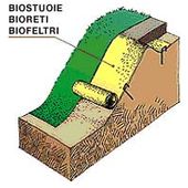
Anti-erosion Solutions
Anti-erosion solutions with the use of bionets: typical scheme.
Typical anti-erosion solutions with geomats.
Typical brushwood solutions.
Anti-erosion solutions with the use of bionets: types of bionets.
Draining techniques
Surface water run off system by prefabricated channels.Micro-perforated flexible drainage tubes.
Drainage systems reduce the water level inside a potentially unstable hillside, which leads to reduction in pore water pressures in the ground and an increase in the shear strength within the slope. Shallow and/or deep drains can reduce the pore pressure, depending on hillside morphology, the kinematics of movement predicted and the depth of creep surfaces. Usually, shallow drainage is adopted where the potential hillside movement is shallow, affecting a depth of 5-6m. Where there are deeper slippage surfaces, deep drainage must be introduced, but shallow drainage systems may also be installed, with the aim of running off surface water.
Shallow drainage
Typical shallow drainage trenches.
Shallow drainage is facilitated through trenches. Traditional drainage trenches are cut in an unbroken length and filled with highly permeable, granular, draining material.
Shallow drainage trenches equipped with geocomposites: typical scheme.
Shallow drainage trenches may also be equipped with geocomposites. The scarped sides of the trenches are covered with geocomposite panels. The bottom of the trenches houses a drainage tube placed in continuity to the geocomposite canvas.
Deep drainage
Deep drainage modifies the filtration routes in the ground. Often more expensive than shallow drains, deep drains are usually more effective because they directly remove the water that induces instability within the hillside.[citation needed] Deep drainage in earth slopes can be achieved in several ways:
Large diameter drainage wells with sub-horizontal drains
These systems can serve a structural function, a drainage function, or both. The draining elements are microdrains, perforated and positioned sub-horizontally and fanned out, oriented uphill to favour water discharge by gravity. The size of the wells is chosen with the aim of allowing the insertion and functioning of the perforation equipment for the microdrains. Generally, the minimum internal diameter is greater than 3.5 m for drains with a length of 20 to 30 m.[citation needed] Longer drains require wells with a diameter of up to 8–10 m.[citation needed] To determine the network of microdrains, planners consider the makeup of the subsoil and the hydraulic regime of the slope.
The drainage in these wells is passive, realised by linking the bottom of adjacent wells by sub-horizontal perforations (provided with temporary sheathing pipes) in which the microdrains are placed at a gradient of about 15-20° and are equipped with microperforated PVC pipes, protected by non-filtering fabric along the draining length. Once the drain is embedded in the ground, the temporary sheathing is completely removed and the head of the drain is cemented to the well. This creates a discharge line linking all the wells emerging to the surface downhill, where the water is discharged naturally without the help of pumps.
The wells are placed at such a distance apart that the individual collecting areas of the microdrains, appertaining to each well, are overlaid. In this way, all the volume of the slope involved with the water table is drained. Medium-diameter drainage wells link at the bottom. The technique involves the dry cutting with temporary sheathing pipes, of aligned drainage wells, with a diameter of 1200–1500mm., positioned at an interaxis of 6–8 m., their bottoms linked together to a bottom tube for the discharge of drained water. In this way, the water discharge takes place passively, due to gravity by perforated pipes with mini-tubes, positioned at the bottom of the wells themselves. The linking pipes, generally made of steel, are blind in the linking length and perforated or windowed in the length corresponding to the well. The wells have a concrete bung at the bottom and are filled, after withdrawal of the temporary sheathing pipe, with dry draining material and are closed with an impermeable clay bung.
In normal conditions, these wells reach a depth of 20–30 m, but, in especially favourable cases, may reach 50 m. Some of these wells have drainage functions across their whole section and others can be inspected. The latter serve for maintenance of the whole drainage screen. Such wells that can be inspected are also a support point for the creation of new drainage wells and access for the installation for a range of sub-horizontal drains at the bottom or along the walls of the wells themselves, with the purpose of increasing the drainage capacity of the well.
Isolated wells fitted with drainage pumps
This system provides for the installation of a drainage pump for each well. The distribution of the wells is established according to the permeability of the land to be drained and the lowering of the water pressure to be achieved. The use of isolated wells with drainage pumps leads to high operational costs and imposes a very time-consuming level of control and maintenance.
Deep drainage trenches
Deep drainage trenches consist of unbroken cuts with a small cross-section that can be covered at the bottom with geofabric canvas having a primary filter function. They are filled with draining material that has a filtering function and exploits the passive drainage to carry away the drained water downhill. The effectiveness of these systems is connected to the geometry of the trench and the continuity of the draining material along the whole trench. As far as the geometry of the cut is concerned attention should be paid to the slope given to the bottom of the cut. In fact, deep drainage trenches do not have bottom piping that is inserted in the end part of the trench, downhill, where the depth of the cut is reduced until the campaign level is reached.
Drainage galleries fitted with microdrains
Drainage galleries constitute a rather expensive stabilisation provision for large, deep landslide movements, used where the ground is unsuitable for cutting trenches or drainage wells and where it is impossible to work on the surface owing to a lack of space for the work machinery. Their effectiveness is due to the extensiveness of the area to be drained. Moreover, these drainage systems must be installed on the stable part of the slope.
Drainage systems made up of microdrains are placed inside galleries with lengths that can reach 50–60 m.[citation needed] The sizes of the galleries are conditioned by the need to insert the drain perforation equipment. For this reason, the minimum transversal internal size of the galleries vary from a minimum of 2 m (when using special reduced size equipment) to at least 3.5 m (when using traditional equipment).[citation needed]
Siphon drain
This is a technique conceived and developed in France, which works like the system of isolated drainage wells but overcoming the inconvenience of installing a pump for each well. Once motion is triggered in the siphon tube without the entry of air into the loop, the flow of water is uninterrupted. For this reason, the two ends of the siphon tube are submerged in the water of two permanent storage tanks. This drain is created vertically starting from the campaign level but can also be sub-vertical or inclined. The diameter of the well can vary from 100 to 300mm. Inside a PVC pipe is placed or a perforated or microperforated steel pipe, filled with draining material. The siphon drain in this way carries off drainage water by gravity without the need for drainage pumps or pipes linking the bottom of each well. This system proves to be economically advantageous and relatively simple to set up, but requires a programme of controls and maintenance.
Microdrains
Microdrains are simple to create drainage systems with contained costs. They consist of small diameter perforations, made from surface locations, in trenches, in wells or in galleries. The microdrains are set to work in a sub-horizontal or sub-vertical position, according to the type of application.
Drainage anti-slide pile (DASP)
The Drainage anti-slide pile (DASP) is a reinforced concrete structure with a hollow upper section and a solid lower section, designed to resist slope deformation.[4][5] The hollow part is filled with compacted, high-permeability gravels and can drain water via a vertical drain-pipe or sub-horizontal pipes connected to the slope surface.[4][5]
Reinforcement measures
Stabilization of a hillside by increasing the mechanical strength of the unstable ground, can be achieved in two ways:
Insertion of reinforcement elements into the ground
The improvement of the mechanical characteristics of the ground through chemical, thermal, or mechanical treatment.
Insertion of reinforcement elements into the ground
Types of mechanical reinforcement include:
Large diameter wells supported by one or more crowns of consolidated, and possibly reinforced earth columns
To guarantee slope stability it may be necessary to insert very rigid, strong elements. These elements are large diameter full section or ring section reinforced concrete wells with circular or elliptical cross-sections. The depth of the static wells can reach 30-40m. Often the static stabilising action of the wells is integrated with a series of microdrains laid out radially on several levels, reducing pore-pressures.
Stabilising an unstable slope also can be achieved by the application of active forces to the unstable ground. These forces increase the normal stress and therefore resistance to friction along the creeping surface. Anchors can be applied for this purpose, linked at the surface to each other by a beam frame, which is generally made of reinforced concrete. The anchors are fixed in a place known to be stable. They are usually installed with orthogonal axes to the slope surface and therefore, at first, approximately orthogonal to the surface of the creep.
Sometimes anchorage problems occur, as in the case of silty-clayey ground. Where there is water or the anchors are embedded in a clayey sub-layer, the adherence of the anchor to the ground must be confirmed. The surface contained within the grid of the beam frame should also be protected, using geofabrics, in order to prevent erosion from removing the ground underlying the beam frame.
Networks of micropiles
This solution requires the installation of a series of micropiles that make up a three-dimensional grid, variably tilted and linked at the head by a rigid reinforced concrete mortise. This structure constitutes a reinforcement for the ground, inducing an intrinsic improvement of the ground characteristics incorporated in the micropiles. This type of measure is used in cases of smaller landslides.
The effectiveness of micropiles is linked to the insertion of micropiles over the entire landslide area. In the case of rotational landslides in soft clay, the piles contribute to increasing the resisting moment by friction on the upper part of the pile shaft found in the landslide. In the case of suspended piles, strength is governed by the part of the pile offering the least resistance. In practice, those piles in the most unstable area of the slope are positioned first, in order to reduce any possible lateral ground displacements.
Preliminary design methods for the micropiles, are entrusted to computer codes that carry out numerical simulations, but which are subject to simplifications in the models that necessitate characterizations of rather precise potential landslide material.
The soil nailing technique applied to temporarily and/or permanently stabilise natural slopes and artificial scarps is based on a fundamental principle in construction engineering: mobilizing the intrinsic mechanical characteristics of the ground, such as cohesion and the angle of internal friction, so that the ground actively collaborates with the stabilisation work. Nailing, on a par with anchors, induces normal stress, thereby increasing friction and stability within the hillside.
One nailing method is rapid response diffuse nailing: CLOUJET, where the nails are embedded in the ground by means of an expanded bulb obtained by means of injecting mortar at high pressure into the anchorage area. Drainage is important to the CLOUJET method since the hydraulic regime, considered in the form of pore-pressure applied normally to the fractured surfaces, directly influences the characteristics of the system. The drained water, both through fabric and by means of pipes embedded in the ground, flows together at the foot of the slope in a collector installed parallel to the direction of the face.
Another nailing system is the soil nail and root technology (SNART). Here, steel nails are inserted very rapidly into a slope by percussion, vibration or screw methods. Grid spacing is typically 0.8 to 1.5 m, nails are 25 to 50mm in diameter and may be as long as 20 m. Nails are installed perpendicular to and through the failure plane, and are designed to resist bending and shear (rather than tension) using geotechnical engineering principles. Potential failure surfaces less than 2 m deep normally require the nails to be wider near the top, which may be achieved with steel plates fastened at the nail heads. Plant roots often form an effective and aesthetic facing to prevent soil loss between the nails.
Geogrids
typical geogrid solution
Geogrids are synthetic materials used to reinforce the ground. The insertion of geosynthetic reinforcements (generally in the direction in which the deformation has developed) has the function of conferring greater stiffness and stability upon the ground, increasing its capacity to be subjected to greater deformations without fracturing.
Cellular faces
Cellular faces, also known by the name of "crib faces" are special supporting walls made of head grids prefabricated in reinforced concrete or wood (treated with preservatives). The heads have a length of about 1–2m and the wall can reach 5 m in height. Compacted granular material is inserted in the spaces of the grid. The modularity of the system confers notable flexibility of use, both in terms of adaptability to the ground morphology, and because the structure does not require a deep foundation other than a laying plane of lean concrete used to make the support plane of the whole structure regular. Vegetation may be planted in the grid spaces, camouflaging of the structure.
Chemical, thermal and mechanical treatments
A variety of treatments may be used to improve the mechanical characteristics of the soil volume affected by landslides. Among these treatments, the technique of jet-grouting is often used, often as a substitute for and/or complement to previously discussed structural measures. The phases of jet-grouting work are:
Perforation phase: insertion, with perforation destroying the nucleus, of a set of poles into the ground up to the depth of treatment required by the project.
Extraction and programmed injection phase: injection of the mixture at very high pressure is done during the extraction phase of the set of poles. It is in this phase that through the insistence of the jet in a certain direction for a certain interval of time, the effect is obtained by the speed of extraction and rotation of the set of poles, so that volumes of ground can be treated in the shape and size desired.
The high energy jet produces a mixture of the ground and a continuous and systematic "claquage" with only a local effect within the radius of action without provoking deformations at the surface that could induce negative consequences on the stability of adjacent constructions.
The projection of the mixture at high speed through the nozzles, using the effect of the elevated energy in play, allows the modification of the natural disposition and mechanical characteristics of the ground in the desired direction and in accordance with the mixture used (cement, bentonite, water, chemical, mixtures etc.). Depending on the characteristics of the natural ground, the type of mixture used, and work parameters, compression strength from 1 to 500 kgf/cm² (100 kPa to 50 MPa) can be obtained in the treated area.
The realisation of massive consolidated ground elements of various shapes and sizes (buttresses and spurs) within the mass to be stabilised, is achieved by acting opportunely on the injection parameters. In this way the following can be obtained: thin diaphragms, horizontal and vertical cylinders of various diameter and generally any geometrical shapes.
Another method for improving the mechanical characteristics of the ground is thermal treatment of potentially unstable hillsides made up of clayey materials. Historically, unstable clayey slopes along railways were hardened by lighting of wood or coal fires within holes dug into the slope. In large diameter holes (from 200 to 400mm.), about 0.8-1.2m. apart and horizontally interconnected, burners were introduced to form cylinders of hardened clay. The temperatures reached were around 800°C. These clay cylinders worked like piles giving greater shear strength to the creep surface. This system was useful for surface creep, as in the case of an embankment. In other cases the depth of the holes or the amount of fuel necessary led to either the exclusion of this technique or made the effort ineffective.
Other stabilisation attempts were made by using electro-osmotic treatment of the ground. This type of treatment is applicable only in clayey grounds. It consists of subjecting the material to the action of a continuous electrical field, introducing pairs of electrodes embedded in the ground. These electrodes, when current is introduced cause the migration of the ion charges in the clay. Therefore, the inter-pore waters are collected in the cathode areas and they are dragged by the ion charges. In this way a reduction in water content is achieved. Moreover, by suitable choice of anodic electrode a structural transformation of the clay can be induced due to the ions freed by the anode triggering a series of chemo-physical reactions improving the mechanical characteristics of the unstable ground.
This stabilisation method, however, is effective only in homogeneous clayey grounds. This condition is hard to find in unstable slopes, therefore electro-osmotic treatment, after some applications, has been abandoned.
See also
Avalanche control– Activities to reduce avalanche hazards, mitigation of a similar disaster type
Cellular confinement– Confinement system used in construction and geotechnical engineering
1 2 Huang, Da; Song, Yi-xiang; Li, Zhao; Luo, Shi-lin; Peng, Jian-bing; Tomás, Roberto (2023-07-01). "Working performance and mechanism of a novel upper-hollow drainage anti-slide pile under the effect of reservoir water fluctuation and precipitation". Acta Geotechnica. 18 (7): 3799–3824. Bibcode:2023AcGtc..18.3799H. doi:10.1007/s11440-022-01775-3. hdl:10045/132005. ISSN1861-1133.
↑ "PS1". Archived from the original on May 5, 2005. Retrieved February 20, 2007.
Further reading
Bomhad E. N. (1986). Stabilità dei pendii, Dario Flaccovio Editore, Palermo.
Cruden D. M. & Varnes D. J. (1996). Landslide types and process. In "Landslides – Investigation and Mitigation", Transportation Research Board special Report n. 247, National Academy Press, Washington DC, 36–75.
Fell R. (1994). Landslide risk assessment and acceptable risk, Can. Geotech. J., vol. 31, 261–272.
Giant G. (1997). Caduta di massi – Analisi del moto e opere di protezione, Hevelius edizioni, Naples.
Hunge O. (1981). Dynamics of rock avalanches and other types of mass movements. PhD Thesis, University of Alberta, Canada.
Peck R.P. (1969). Advantages and limitations of the observational method in applied soil mechanics, Geotechnique 19, n. 2, 171–187.
Tambura F. (1998). Stabilizzazione di pendii – Tipologie, tecnologie, realizzazioni, Hevelius edizioni, Naples.
Tanzini M. (2001). Fenomeni franosi e opere di stabilizzazione, Dario Flaccovio Editore, Palermo
Terzaghi K. & Peck R. B. (1948). Soil mechanics in engineering practice, New York, Wiley.
Coir Green (1998). " Erosion Control – Soil Erosion
This page is based on this Wikipedia article Text is available under the CC BY-SA 4.0 license; additional terms may apply. Images, videos and audio are available under their respective licenses.


 Anti-erosion solutions with the use of bionets: typical scheme.
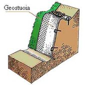 Typical anti-erosion solutions with geomats.
 Typical brushwood solutions.
 Anti-erosion solutions with the use of bionets: types of bionets.


