Succeeding the original MOS Technology VIC used in the VIC-20, the VIC-II was one of the key custom chips in the Commodore 64 (the other being the MOS Technology 6581 sound chip).
Development history
The VIC-II chip was designed primarily by Albert Charpentier and Charles Winterble[1] at MOS Technology, Inc. as a successor to the MOS Technology 6560 "VIC". The team at MOS Technology had previously failed to produce two graphics chips named MOS Technology 6562 for the Commodore TOI computer, and MOS Technology 6564 for the Color PET, due to memory speed constraints.[2]
In order to construct the VIC-II, Charpentier and Winterble made a market survey of current home computers and video games, listing up the current features, and what features they wanted to have in the VIC-II. The idea of adding sprites came from the TI-99/4A computer and its TMS9918graphics coprocessor. The idea to support collision detection came from the Mattel Intellivision. The Atari 800 was also mined for desired features, particularly bitmap mode, which was a desired goal of the MOS team as all of Commodore's principal home computer rivals had bitmap graphics while the VIC-20 only had redefinable characters.[3][4] About 3/4 of the chip surface is used for the sprite functionality.[5]
The chip was partly laid out using electronic design automation tools from Applicon (now a part of UGS Corp.), and partly laid out manually on vellum paper. The design was partly debugged by fabricating chips containing small subsets of the design, which could then be tested separately. This was easy since MOS Technology had both its research and development lab and semiconductor plant at the same location. The initial batch of test chips came out almost fully functional, with only one bad sprite.[6] The chip was developed in 5 micrometer technology.[3]
The work on the VIC-II was completed in November 1981 while Robert Yannes was simultaneously working on the SID chip. Both chips, like the Commodore 64, were finished in time for the Consumer Electronics Show in the first weekend of January 1982.[7]
VIC-II features
Some of the graphics modes on the 64 are really strange, and they have no analogs to the Atari or Apple, like the ability to change color of the character basis across the screen. That gave us a lot of color capability that had not been exploited.
Bus mastering for a 6502-style system bus; CPU and VIC-II accessing the bus during alternating half-clock cycles (the VIC-II will halt the CPU when it needs extra cycles)
Note that below register addresses are stated as seen by CPU in a C64. To yield the register numbers as usually given in data sheets (i.e. starting with 0), the leading "D0" should be omitted.
Programming
Supratechnic, a type-in program published by COMPUTE!'s Gazette in November 1988, showcases the careful use of raster interrupts to display information outside of the standard screen borders (here: the upper and lower border).
The VIC-II is programmed by manipulating its 47 control registers (up from 16 in the VIC), memory mapped to the range $D000–$D02E in the C64 address space. Of all these registers, 34 deal exclusively with sprite control (sprites being called MOBs, from "Movable Object Blocks", in the VIC-II documentation). Like its predecessor, the VIC-II handles light pen input, and with help from the C64's standard character ROM, provided the original PETSCII character set from 1977 on a similarly dimensioned display as the 40-column PET series.
By reloading the VIC-II's control registers via machine code hooked into the raster interrupt routine (the scanline interrupt), one can program the chip to generate significantly more than 8 concurrent sprites (a process known as sprite multiplexing), and generally give every program-defined slice of the screen different scrolling, resolution and color properties. The hardware limitation of 8 sprites per scanline can be increased further by letting the sprites flicker rapidly on and off. Mastery of the raster interrupt is essential in order to unleash the VIC-II's capabilities. Many demos and some later games would establish a fixed "lock-step" between the CPU and the VIC-II so that the VIC registers could be manipulated at exactly the right moment, but the reliance on raster interrupts to ensure proper synchronization could be reduced and their overhead minimized.
Character graphics
The C64 shipped with the PETSCII character set in a 4k ROM, but, like the VIC-20 before it, the actual data for the characters was read from memory at a specified location. This location is one of the VIC-II registers, which allowed programmers to construct their own characters sets by placing the appropriate data in memory; each character is an 8x8 grid, a byte representing 8 bits horizontally, so 8 bytes are required for a single character and thus the complete 256-character set uses a total of 2,048 bytes. Theoretically as many as eight character sets can be used if the entire 16k of video memory were filled.[9]:363
In addition to charsets, the VIC-II also uses 1000 bytes to store the 25 lines of 40 characters per line, one byte for each character, which in power on default configuration sits at $400-$7E8.[9]:117–119 Color RAM is accessed as bits 8 to 11 of the video matrix;[10] in the 64 and 128, it is located in I/O space at $D800-$DBFF and cannot be moved from that location. It contains the values for color 1 (color 3 in multicolor mode) of each character.
The character ROM is mapped into two of the VIC-II's four "windows", at $1000-$1FFF and $9000-$9FFF, although the CPU cannot see it there (the character ROM may be switched into $D000-$DFFF where it is visible to the CPU, but not the VIC-II). Thus graphics data or video buffers cannot be placed at $1000-$1FFF or $9000-$9FFF because the VIC-II will see the character ROM there instead. Because these areas of RAM could not be used by the VIC-II graphics chip, they were frequently used for music/sound effects (the SID chip). The C64 has the ability to have RAM and ROM at the same address in memory but the CPU would "see" one and the VIC-II chip would "see" the other.
In default high-resolution character mode, the foreground of each character may be set individually in the color RAM. In multicolor character mode, color 3 is limited to the first eight possible color values; the fourth bit is then used as a flag indicating if this character is to be displayed in high-resolution or multicolor, thus making it possible to mix both types on one screen.[9]:460–462 Colors 1 and 2 are set by the registers at $D022 and $D023 and are global for all characters.[9]:373
If Extended Background Color Mode is used, the upper two bits of the character code are used to select one of four background color registers. This allows four different background colors on the screen, but at the expense of only allowing 64 different characters instead of 256. Because this is limiting, games seldom used it.
Bitmap mode
Adding an all-points-addressable bitmap mode was one of the Commodore design team's primary goals, as the VIC-I lacked such a feature. However, in order to use as little additional circuitry as possible, they organized it in the same manner as character mode, i.e. 8x8 and 4x8 tiles. Bitmap graphics require an 8k page for the pixel data and each byte corresponds to one row of eight or four pixels. The next byte is the row underneath it and after the 8th row, returning to the top of the next tile.
In hi-res bitmaps, screen RAM is used to hold the foreground and background colors of each tile (high and low nibble of each byte). This is the only VIC-II mode that does not make any use of the color RAM at $D800 or the background color register at $D021.
Multicolor bitmap mode allows three colors per tile (the fourth is the background color as set in $D021). Colors 1 and 2 are selected by the bits in screen RAM (same as hires bitmaps) and the third is from color RAM.
Despite the high level of color detail and all-points-addressable capabilities of bitmap mode, it is generally impractical for in-game graphics due to requiring a high amount of system resources (8k for the pixel data plus considerable more CPU cycles to modify each tile) and normally cannot be scrolled. Thus, it is most commonly seen on loader and sometimes title screens.
Sprites
VIC-II sprites are either 24x21 monochrome or 12x21 multicolor. Similar to character graphics, the latter have one individual color for each sprite and two global ones. VIC-II has eight sprites, each of which uses 64 bytes of memory to store but, with certain limitations, it can display many more. Sprite multiplexing is a common method of getting more than eight on screen (although there still is a maximum of eight per scan line). The VIC-II scanline counter can be polled until the desired point is reached on screen, or a raster interrupt can be programmed to trigger at a certain scanline, after which the program quickly changes the sprite coordinates. This method can result in many additional sprites onscreen at once, often for a total of 16 to 24 or more. For a demo, though, the limit is considerably more flexible.
In theory the maximum number of different sprites visible at the same time is 256 (assuming the VIC-II's entire 16k page was filled). They are addressed by using a block number to refer to each sprite pattern in memory beginning with 0 and going to 255 ($FF) depending on their position in the video page. (if the second video bank (numbered as 0 1 2 and 3) is used, Block 0 would refer to the sprite stored at $4000 and Block 255 would be at $7FC0).
Each sprite may be double-sized vertically, horizontally or both. This does not increase the sprite resolution (it is still 24 pixels wide and 21 tall) but each pixel will be twice as wide and/or twice as tall.
Because the horizontal position register for each sprite is one byte and limited to a maximum value of 255, it alone cannot cover the entire 320 pixels of the VIC-II's screen area, so an additional register called the Most Significant Byte Flag provides a 9th position bit for all sprites.
$D01E and $D01F contain the Background and Sprite-to-Sprite Collision registers. The former is rarely used because it cannot provide information on the specific background object the sprite is touching.
$D01B contains the Sprite To Background priority register, which is used to govern whether a sprite moves behind or in front of background graphics. When a sprite enters the same space as another sprite, the lower-numbered ones will always pass over the higher numbered ones.
Scrolling
In order to scroll a character screen, the VIC-II is set to 38-column and/or 24-line mode via the registers at $D011 and $D016. This creates an off-screen buffer where the row of characters to be scrolled is placed. By adjusting the scroll bits in the above-mentioned registers, one row may be moved on-screen after which it repeats unless a new row is put in the buffer. Color RAM is scrolled simultaneous with screen RAM and works the same way.
VIC-II scrolling is a relatively complicated, CPU intensive task, although it is not uncommon for C64 game programmers to cheat by designing graphics so that the color RAM can remain static. Another standard trick is to use a section of the screen (perhaps the bottom or top 4 or 5 character rows) as a game status area to display score, lives, etc. reducing the amount of scrolling that has to be performed. Finally, it is often necessary to use the "double-buffering" technique to prevent screen tearing. Two 1k blocks of screen ram are reserved; one is displayed while another is written to, then during vblank they are quickly swapped through manipulation of the VIC-II registers. Unfortunately this cannot be done with color RAM.
Late in the C64's commercial lifespan, an exploit known as VSP (Variable Screen Positioning) was discovered that involved manipulation of the control bits in $D011 to produce fast scrolling at a much lower CPU cycle cost than the standard scroll registers, however it required careful, cycle-exact coding and did not work reliably on some VIC-II revisions; also it can only be used for horizontal scrolling. It is notably used in Mayhem in Monsterland.
Raster interrupts
Utilization of raster interrupts is an essential part of C64 game programming. In the computer's power-on default state, the first MOS Technology CIA chip generates a maskable interrupt (IRQ) 60 times per second (whether NTSC or PAL, this is unrelated to video refresh) which sends the CPU to the kernel IRQ handler at $EA31. The handler acknowledges the CIA's IRQ, updates the clock, scans the keyboard, and blinks the cursor in BASIC.
Games normally disable the CIA's interrupt and instead set up the VIC-II to generate interrupts when a specific scanline is reached, which is necessary for split-screen scrolling and playing music. The game remaps the IRQ vector at $0314/$0315 to its raster handler which performs these functions and then optionally executes a JMP $EA31 instruction to return control to the kernel.
Some games use only one IRQ; however, chained IRQs are more common and improve program stability. In this setup, the IRQ is remapped to the second routine and so forth for each one until the last one restores it to the address of the first IRQ. When chained IRQs are used, only one JMP $EA31 instruction is needed in the chain and the others can be ended with JMP $EA81, which simply goes to the end of the kernel handler. Also it is not uncommon for games to switch out the kernal and use their own IRQ handler instead. The NMI can be used for an additional interrupt thread, although undesirable side effects can result from accidentally pressing the Restore key as it triggers an NMI if pressed.
The VIC-II may also generate a raster interrupt from the collision registers, but this feature is rarely used as it provides insufficient information to the program in most cases.
Memory mapping
The VIC-II has a 14-bit address bus and can use any of the four 16k segments of the C64's memory space for video data. To manage this, two additional address bits are contributed by port bits of CIA. $0000-$3FFF is the power-on default. The second segment ($4000–$7FFF) is typically the best choice for programming from BASIC as it is the only segment that is completely free RAM with no ROMs or I/O registers mapped into it. The fourth segment ($C000–$FFFF) is also a good choice provided that machine language is used, as the kernel ROMs must be disabled to gain read access by the CPU, and it avoids having discontiguous program code and data that would result from using $4000-$7FFF. Note that graphics data may be freely stored underneath the BASIC ROM at $A000-$BFFF, the kernel ROM at $E000-$FFFF or I/O registers and color RAM at $D000–$DFFF, since the VIC-II only sees RAM, regardless of how the CPU memory mapping is adjusted; character ROM is visible only in the first and third segment, thus if segment two or four is used, the programmer must supply his own character data. The screen RAM, bitmap page, sprites, and character sets must all occupy the same segment window (provided the CIA bits aren't changed via scanline interrupt). The last six bytes of system memory ($FFFA-$FFFF) contain the IRQ, NMI, and reset vectors so if the top of memory is used to store a character set or sprite data, and the KERNAL ROM is switched out revealing the RAM underneath to the CPU, it will be necessary to sacrifice one character or sprite to avoid overwriting the vectors.
Registers
The VIC-II has 47 read/write registers listed below:
Register
Hexadecimal
Bit 7
Bit 6
Bit 5
Bit 4
Bit 3
Bit 2
Bit 1
Bit 0
Description
0
D000
M0X
X Coordinate Sprite 0
1
D001
M0Y
Y Coordinate Sprite 0
2
D002
M1X
X Coordinate Sprite 1
3
D003
M1Y
Y Coordinate Sprite 1
4
D004
M2X
X Coordinate Sprite 2
5
D005
M2Y
Y Coordinate Sprite 2
6
D006
M3X
X Coordinate Sprite 3
7
D007
M3Y
Y Coordinate Sprite 3
8
D008
M4X
X Coordinate Sprite 4
9
D009
M4Y
Y Coordinate Sprite 4
10
D00A
M5X
X Coordinate Sprite 5
11
D00B
M5Y
Y Coordinate Sprite 5
12
D00C
M6X
X Coordinate Sprite 6
13
D00D
M6Y
Y Coordinate Sprite 6
14
D00E
M7X
X Coordinate Sprite 7
15
D00F
M7Y
Y Coordinate Sprite 7
16
D010
M7X8
M6X8
M5X8
M4X8
M3X8
M2X8
M1X8
M0X8
MSBs of X coordinates
17
D011
RST8
ECM
BMM
DEN
RSEL
YSCROLL
Control register 1
18
D012
RST
Raster counter
19
D013
LPX
Light Pen X
20
D014
LPY
Light Pen Y
21
D015
M7E
M6E
M5E
M4E
M3E
M2E
M1E
M0E
Sprite enabled
22
D016
—
—
RES
MCM
CSEL
XSCROLL
Control register 2
23
D017
M7YE
M6YE
M5YE
M4YE
M3YE
M2YE
M1YE
M0YE
Sprite Y expansion
24
D018
VM13
VM12
VM11
VM10
CB13
CB12
CB11
—
Memory pointers
25
D019
IRQ
—
—
—
ILP
IMMC
IMBC
IRST
Interrupt register
26
D01A
—
—
—
—
ELP
EMMC
EMBC
ERST
Interrupt enabled
27
D01B
M7DP
M6DP
M5DP
M4DP
M3DP
M2DP
M1DP
M0DP
Sprite data priority
28
D01C
M7MC
M6MC
M5MC
M4MC
M3MC
M2MC
M1MC
M0MC
Sprite multicolor
29
D01D
M7XE
M6XE
M5XE
M4XE
M3XE
M2XE
M1XE
M0XE
Sprite X expansion
30
D01E
M7M
M6M
M5M
M4M
M3M
M2M
M1M
M0M
Sprite-sprite collision
31
D01F
M7D
M6D
M5D
M4D
M3D
M2D
M1D
M0D
Sprite-data collision
32
D020
—
—
—
—
EC
Border color
33
D021
—
—
—
—
B0C
Background color 0
34
D022
—
—
—
—
B1C
Background color 1
35
D023
—
—
—
—
B2C
Background color 2
36
D024
—
—
—
—
B3C
Background color 3
37
D025
—
—
—
—
MM0
Sprite multicolor 0
38
D026
—
—
—
—
MM1
Sprite multicolor 1
39
D027
—
—
—
—
M0C
Color sprite 0
40
D028
—
—
—
—
M1C
Color sprite 1
41
D029
—
—
—
—
M2C
Color sprite 2
42
D02A
—
—
—
—
M3C
Color sprite 3
43
D02B
—
—
—
—
M4C
Color sprite 4
44
D02C
—
—
—
—
M5C
Color sprite 5
45
D02D
—
—
—
—
M6C
Color sprite 6
46
D02E
—
—
—
—
M7C
Color sprite 7
Colors
The VIC-II chip has a fixed 16-color palette, shown above.
In multicolor character mode (160×200 pixels, which most games use) characters have 4×8 pixels (the characters are still approximately square since the pixels are double width) and 4 colors out of 16 colors. Three of the colors are the same for the entire screen (the background color, multicolor 1, and multicolor 2 registers), while the remaining color can be set individually for every such 4×8 pixel area as defined in color RAM. Sprites in multicolor mode (12×21 pixels) have three colors plus transparency: two colors shared among all sprites and one individual. Artists pick shared colors such that the combination with individual colors leads to a colorful impression. Some games reload shared colors during the raster interrupt; for example, the game Turrican II's underwater area (which was vertically distinct) has different colors. Others, such as Epyx's Summer Games and COMPUTE!'s Gazette's Basketball Sam & Ed, overlay two high-resolution sprites to allow two foreground colors to be used without sacrificing horizontal resolution . Of course, this technique reduces the number of available sprites by half.
On PAL C64s, the PAL delay line in the monitor or TV which averages the color hue, but not the brightness, of consecutive screen lines can be used to create seven nonstandard colors by alternating screen lines showing two colors of identical brightness. There are seven such pairs of colors in the VIC chip.[11]
The C64's team did not spend much time on mathematically computing the 16 color palette. Robert Yannes, who was involved with the development of the VIC-II, said:
I'm afraid that not nearly as much effort went into the color selection as you think. Since we had total control over hue, saturation and luminance, we picked colors that we liked. In order to save space on the chip, though, many of the colors were simply the opposite side of the color wheel from ones that we picked. This allowed us to reuse the existing resistor values, rather than having a completely unique set for each color.[12]
Early versions of the VIC-II used in PAL C64s have a different color palette than later revisions.[13]
The full palette of sixteen colors is generated based on variations of YPbPr signals as shown below:
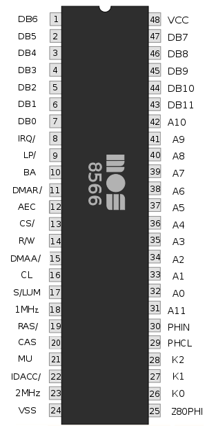
The 8564/8566 VIC-IIe in the Commodore 128 uses 48 pins rather than 40, as it produces more signals, among them the clock for the additional Zilog Z80 CPU of that computer. It also has two extra registers. One of the additional registers is for accessing the added numerical keypad and other extra keys of that computer; this function was added to the VIC merely because that proved to be the easiest place in the computer to add the necessary three extra output pins. The other extra register is for toggling between a 1MHz and a 2MHz system clock; at the higher speed the VIC-II's video output is merely displaying every second byte in the code as black hires bit-pattern on the screen, suggesting use of the C128's 80-column mode at that speed (via the 8563 VDC RGB chip). Rather unofficially, the two extra registers are also available in the C128's C64 mode, permitting some use of the extra keys, as well as double-speed-no-video execution of CPU-bound code (such as intensive numerical calculations) in self-made C64 programs.[14] The extra registers are also one source of minor incompatibility between the C128's C64 mode and a real C64 - a few older C64 programs inadvertently wrote into the 2MHz toggle bit, which would do nothing at all on a real C64, but would result in a messed-up display on a C128 in C64 mode.
The VIC-IIe has the little-known ability to create an additional set of colors by manipulating the registers in a specific way that puts the color signal out of phase with what other parts of the chip consider it to be in.[citation needed] This ability was demonstrated in the "Risen from Oblivion" demo. [15] Unfortunately it does not work on all monitors - correct colors are confirmed on Commodore CRT monitors and their equivalents.
Using the specific behavior of the VIC-IIe's test bit, it is furthermore capable of producing a real interlace picture with a resolution of 320×400 (hires mode) and 160×400 (multicolor mode).[16]
List of VIC-II versions
Commodore made many modifications to the VIC-II during its lifetime. Compute!'s Gazette's first issue, in July 1983, reported that there had already been eight since the Commodore 64's release in mid-1982.[17]
MOS Technology 6569 – (PAL-B, used in most PAL countries)
MOS Technology 6572 – (PAL-N, used in southern South America only)
MOS Technology 6573 – (PAL-M, used in Brazil only)
MOS Technology 8565 – HMOS-II version for "C64E" motherboards
MOS Technology 8566 – VIC-II E (PAL-B) C128 version
MOS Technology 8569 – VIC-II E (PAL-N) C128 version
The earliest revision of the VIC-II was used in machines made during 1982 and early 1983; it had a ceramic shell for thermal reasons and generated 64 NTSC color clocks per line. These chips also did not output separated chroma and luminance signals. Later revisions had a lower cost plastic shell and 65 color clocks per line (for NTSC, 63 for PAL), as well as separated chroma and luminance, allowing for an early form of S-video. Several revisions were made chiefly in the interest of improving video output quality, which was poor on the early units, and eliminating a bug that would cause random pixels to appear on screen (a few early games intentionally exploited this for graphics effects that consequently did not work on later C64s). The 64 color clocks on the initial VIC-II was done with the intention of allowing NTSC artifact color in high resolution bitmap mode as the Atari 8-bit computers did, but that idea was quickly dropped.
Because it was necessary for cost reasons to switch to a plastic shell, overheating tended to be a problem with the VIC-II. This was for several reasons including the high density of the die relative to the process used, and its high internal speed (8MHz). Commodore tried an impromptu solution for this by using the aluminum RF shield as a heat sink (on NTSC machines; PAL machines were sold in countries with less restrictive RF interference standards than the United States and so only used aluminized cardboard), however it was not entirely effective at preventing overheating and chip failure.
The 85xx VIC-II used in C64Cs was made with the more modern 3.5 μm HMOS process and requires only a single 5V power rail instead of the dual 12V and 5V rails of the 65xx VIC-II. These chips run significantly cooler and do not suffer from the overheating issues that affect the 65xx VIC-II.
Several revisions of 6569 exist: 6569R1 (usually gold plated), 6569R3, 6569R4 and 6569R5. The most common version of 8565 is 8565R2.
↑Bagnall, Brian (2005). "The Secret Project 1981". On the Edge: The Spectacular Rise and Fall of Commodore (1ed.). Winnipeg, Manitoba: Variant Press. pp.224–225. ISBN0-9738649-0-7.
↑Bagnall, Brian (2005). "The Secret Project 1981". On the Edge: The Spectacular Rise and Fall of Commodore (1ed.). Winnipeg, Manitoba: Variant Press. p.227. ISBN0-9738649-0-7.
↑Bagnall, Brian (2005). "The Secret Project 1981". On the Edge: The Spectacular Rise and Fall of Commodore (1ed.). Winnipeg, Manitoba: Variant Press. p.229. ISBN0-9738649-0-7.
↑Bagnall, Brian (2005). "The Secret Project 1981". On the Edge: The Spectacular Rise and Fall of Commodore (1ed.). Winnipeg, Manitoba: Variant Press. p.230. ISBN0-9738649-0-7.
↑Bagnall, Brian (2005). "The Secret Project 1981". On the Edge: The Spectacular Rise and Fall of Commodore (1ed.). Winnipeg, Manitoba: Variant Press. p.242. ISBN0-9738649-0-7.
Description of C64 graphics modes - simple explanations with example pictures of the common modes used for C64 graphics, including hacked and software-assisted modes.
This page is based on this Wikipedia article Text is available under the CC BY-SA 4.0 license; additional terms may apply. Images, videos and audio are available under their respective licenses.