Power rating

Last updated

In electrical engineering and mechanical engineering, the power rating of equipment is the highest power input allowed to flow through particular equipment. According to the particular discipline, the term power may refer to electrical or mechanical power. A power rating can also involve average and maximum power, which may vary depending on the kind of equipment and its application.

Contents

Power rating limits are usually set as a guideline by the manufacturers, protecting the equipment and simplifying the design of larger systems, by providing a level of operation under which the equipment will not be damaged while allowing for a certain safety margin.

Equipment types

Dissipative equipment

In equipment which primarily dissipate electric power or convert it into mechanical power, such as resistors, and speakers, the power rating given is usually the maximum power that can be safely dissipated by the equipment. The usual reason for this limit is heat, although in certain electromechanical devices, particularly speakers, it is to prevent mechanical damage. When heat is the limiting factor, the power rating is easily calculated. First, the amount of heat that can be safely dissipated by the device, , must be calculated. This is related to the maximum safe operating temperature, the ambient temperature or temperature range in which the device will be operated, and the method of cooling. If is the maximum safe operating temperature of the device, is the ambient temperature, and is the total thermal resistance between the device and ambient, then the maximum heat dissipation is given by

If all power in a device is dissipated as heat, then this is also the power rating.

Mechanical equipment

Equipment is generally rated by the power it will deliver, for example, at the shaft of an electric or hydraulic motor. The power input to the equipment will be greater owing to the less than 100% efficiency of the device. [1] [2] [3] Efficiency of a device is often defined as the ratio of output power to the sum of output power and losses. In some types of equipment it is possible to measure or calculate losses directly. This allows efficiency to be calculated with greater precision than the quotient of input power over output power, where relatively small measurement uncertainty will greatly affect the resulting calculated efficiency.

Power converting equipment

In devices that primarily convert between different forms of electric power, such as transformers, or transport it from one location to another, such as transmission lines, the power rating almost always refers to the maximum power flow through the device, not dissipation within it. The usual reason for the limit is heat, and the maximum heat dissipation is calculated as above.

Power ratings are usually given in watts for real power and volt-amperes for apparent power, although for devices intended for use in large power systems, both may be given in a per-unit system. Cables are usually rated by giving their maximum voltage and their ampacity. [4] As the power rating depends on the method of cooling, different ratings may be specified for air cooling, water cooling, etc. [4]

Average vs. maximum

For AC-operated devices (e.g. coaxial cable, loudspeakers), there may even be two power ratings, a maximum (peak) power rating and an average power rating. [5] [6] For such devices, the peak power rating usually specifies the low frequency or pulse energy, while the average power rating limits high-frequency operation. [5] Average power calculation rating depends on some assumptions how the device is going to be used. For example, the EIA rating method for loudspeakers uses a shaped noise signal that simulates music and allows peak excursion of 6 dB, so an EIA rating of 50 Watts corresponds to 200 Watts peak rating. [6]

Maximum continuous rating

Maximum continuous rating (MCR) is defined as the maximum output (MW) that an electric power generating station is capable of producing continuously under normal conditions over a year. Under ideal conditions, the actual output could be higher than the MCR. [7]

Within shipping, ships usually operates at the nominal continuous rating (NCR) which is 85% of the 90% of MCR. The 90% MCR is usually the contractual output for which the propeller is designed. Thus, the usual output at which ships are operated is around 75% to 77% of MCR. [8]

Other definitions

In some fields of engineering, even a more complex set of power ratings is used. For example, helicopter engines are rated for continuous power (which does not have a time constraint), takeoff and hover power rating (defined as half to one hour operation), maximum contingency power (which can be sustained for two-three minutes), and emergency (half a minute) power rating. [9]

For electrical motors, a similar kind of information is conveyed by the service factor, which is a multiplier that, when applied to the rated output power, gives the power level a motor can sustain for shorter periods of time. The service factor is typically in the 1.15-1.4 range, with the figure being lower for higher-power motors. For every hour of operation at the service-factor-adjusted power rating, a motor loses two to three hours of life at nominal power, i.e. its service life is reduced to less than half for continued operation at this level. [4] [10] The service factor is defined in the ANSI/NEMA MG 1 standard, [11] and is generally used in the United States. [12] There is no IEC standard for the service factor. [13]

Exceeding the power rating of a device by more than the margin of safety set by the manufacturer usually does damage to the device by causing its operating temperature to exceed safe levels. In semiconductors, irreparable damage can occur very quickly. Exceeding the power rating of most devices for a very short period of time is not harmful, although doing so regularly can sometimes cause cumulative damage.

Power ratings for electrical apparatus and transmission lines are a function of the duration of the proposed load and the ambient temperature; a transmission line or transformer, for example, can carry significantly more load in cold weather than in hot weather. Momentary overloads, causing high temperatures and deterioration of insulation, may be considered an acceptable trade-off in emergency situations. The power rating of switching devices varies depending on the circuit voltage as well as the current. In certain aerospace or military applications, a device may carry a much higher rating than would be accepted in devices intended to operate for long service life.

Examples

Audio amplifiers

Audio amplifier power ratings are typically established by driving the device under test to the onset of clipping, to a predetermined distortion level, variable per manufacturer or per product line. Driving an amplifier to 1% distortion levels will yield a higher rating than driving it to 0.01% distortion levels. [14] Similarly, testing an amplifier at a single mid-range frequency, or testing just one channel of a two-channel amplifier, will yield a higher rating than if it is tested throughout its intended frequency range with both channels working. Manufacturers can use these methods to market amplifiers whose published maximum power output includes some amount of clipping in order to show higher numbers. [14]

For instance, the Federal Trade Commission (FTC) established an amplifier rating system in which the device is tested with both channels driven throughout its advertised frequency range, at no more than its published distortion level. The Electronic Industries Association (EIA) rating system, however, determines amplifier power by measuring a single channel at 1,000 Hz, with a 1% distortion level—1% clipping. Using the EIA method rates an amplifier 10 to 20% higher than the FTC method. [14]

Photovoltaic modules

The nominal power of a photovoltaic module is determined by measuring current and voltage while varying resistance under defined illumination. The conditions are specified in standards such as IEC 61215, IEC 61646 and UL 1703; specifically, the light intensity is 1000 W/m2, with a spectrum similar to sunlight hitting the Earth's surface at latitude 35° N in the summer (airmass  1.5) and temperature of the cells at 25 °C. The power is measured while varying the resistive load on the module between open and closed circuit.

The maximum power measured is the nominal power of the module in Watts. Colloquially, this is also written as "Wp"; this format is colloquial as it is outside the standard by adding suffixes to standardized units. The nominal power divided by the light power that falls on the module (area x 1000 W/m2) is the efficiency.

See also

Related Research Articles

In electronics, the figures of merit of an amplifier are numerical measures that characterize its properties and performance. Figures of merit can be given as a list of specifications that include properties such as gain, bandwidth, noise and linearity, among others listed in this article. Figures of merit are important for determining the suitability of a particular amplifier for an intended use.

<span class="mw-page-title-main">Amplifier</span> Electronic device/component that increases the strength of a signal

An amplifier, electronic amplifier or (informally) amp is an electronic device that can increase the magnitude of a signal. It is a two-port electronic circuit that uses electric power from a power supply to increase the amplitude of a signal applied to its input terminals, producing a proportionally greater amplitude signal at its output. The amount of amplification provided by an amplifier is measured by its gain: the ratio of output voltage, current, or power to input. An amplifier is defined as a circuit that has a power gain greater than one.

<span class="mw-page-title-main">Heat engine</span> System that converts heat or thermal energy to mechanical work

A heat engine is a system that converts heat to usable energy, particularly mechanical energy, which can then be used to do mechanical work. While originally conceived in the context of mechanical energy, the concept of the heat engine has been applied to various other kinds of energy, particularly electrical, since at least the late 19th century. The heat engine does this by bringing a working substance from a higher state temperature to a lower state temperature. A heat source generates thermal energy that brings the working substance to the higher temperature state. The working substance generates work in the working body of the engine while transferring heat to the colder sink until it reaches a lower temperature state. During this process some of the thermal energy is converted into work by exploiting the properties of the working substance. The working substance can be any system with a non-zero heat capacity, but it usually is a gas or liquid. During this process, some heat is normally lost to the surroundings and is not converted to work. Also, some energy is unusable because of friction and drag.

<span class="mw-page-title-main">Loudspeaker</span> Converts an electrical audio signal into a corresponding sound

A loudspeaker is an electroacoustic transducer that converts an electrical audio signal into a corresponding sound. A speaker system, also often simply referred to as a speaker or loudspeaker, comprises one or more such speaker drivers, an enclosure, and electrical connections possibly including a crossover network. The speaker driver can be viewed as a linear motor attached to a diaphragm which couples that motor's movement to motion of air, that is, sound. An audio signal, typically from a microphone, recording, or radio broadcast, is amplified electronically to a power level capable of driving that motor in order to reproduce the sound corresponding to the original unamplified electronic signal. This is thus the opposite function to the microphone; indeed the dynamic speaker driver, by far the most common type, is a linear motor in the same basic configuration as the dynamic microphone which uses such a motor in reverse, as a generator.

A woofer or bass speaker is a technical term for a loudspeaker driver designed to produce low frequency sounds, typically from 20 Hz up to a few hundred Hz. A subwoofer can take the lower part of this range, normally up to 80 Hz. The name is from the onomatopoeic English word for a dog's deep bark, "woof". The most common design for a woofer is the electrodynamic driver, which typically uses a stiff paper cone, driven by a voice coil surrounded by a magnetic field.

<span class="mw-page-title-main">Power inverter</span> Device that changes direct current (DC) to alternating current (AC)

A power inverter, inverter, or invertor is a power electronic device or circuitry that changes direct current (DC) to alternating current (AC). The resulting AC frequency obtained depends on the particular device employed. Inverters do the opposite of rectifiers which were originally large electromechanical devices converting AC to DC.

Audio power is the electrical power transferred from an audio amplifier to a loudspeaker, measured in watts. The electrical power delivered to the loudspeaker, together with its efficiency, determines the sound power generated.

<span class="mw-page-title-main">Audio system measurements</span> Means of quantifying system performance

Audio system measurements are a means of quantifying system performance. These measurements are made for several purposes. Designers take measurements so that they can specify the performance of a piece of equipment. Maintenance engineers make them to ensure equipment is still working to specification, or to ensure that the cumulative defects of an audio path are within limits considered acceptable. Audio system measurements often accommodate psychoacoustic principles to measure the system in a way that relates to human hearing.
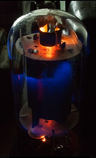
The efficiency of a system in electronics and electrical engineering is defined as useful power output divided by the total electrical power consumed, typically denoted by the Greek small letter eta.

<span class="mw-page-title-main">Torque converter</span> Fluid coupling that transfers rotating power from a prime mover to a rotating driven load

A torque converter is a device, usually implemented as a type of fluid coupling, that transfers rotating power from a prime mover, like an internal combustion engine, to a rotating driven load. In a vehicle with an automatic transmission, the torque converter connects the prime mover to the automatic gear train, which then drives the load. It is thus usually located between the engine's flexplate and the transmission. The equivalent device in a manual transmission is the mechanical clutch.

<span class="mw-page-title-main">Voltage regulator</span> System designed to maintain a constant voltage

A voltage regulator is a system designed to automatically maintain a constant voltage. It may use a simple feed-forward design or may include negative feedback. It may use an electromechanical mechanism, or electronic components. Depending on the design, it may be used to regulate one or more AC or DC voltages.

<span class="mw-page-title-main">Damping factor</span> Ratio of impedance of a loudspeaker

In an audio system, the damping factor is defined as the ratio of the rated impedance of the loudspeaker to the source impedance of the power amplifier. It was originally proposed in 1941. Only the magnitude of the loudspeaker impedance is used, and the power amplifier output impedance is assumed to be totally resistive.

<span class="mw-page-title-main">Output impedance</span> Measure of the opposition to current flow by an internal electrical load

In electrical engineering, the output impedance of an electrical network is the measure of the opposition to current flow (impedance), both static (resistance) and dynamic (reactance), into the load network being connected that is internal to the electrical source. The output impedance is a measure of the source's propensity to drop in voltage when the load draws current, the source network being the portion of the network that transmits and the load network being the portion of the network that consumes.

<span class="mw-page-title-main">Variable-frequency drive</span> Type of adjustable-speed drive

A variable-frequency drive is a type of AC motor drive that controls speed and torque by varying the frequency of the input electricity. Depending on its topology, it controls the associated voltage or current variation.

<span class="mw-page-title-main">Class-D amplifier</span> Audio amplifier based on switching

A class-D amplifier or switching amplifier is an electronic amplifier in which the amplifying devices operate as electronic switches, and not as linear gain devices as in other amplifiers. They operate by rapidly switching back and forth between the supply rails, using pulse-width modulation, pulse-density modulation, or related techniques to produce a pulse train output. A simple low-pass filter may be used to attenuate their high-frequency content to provide analog output current and voltage. Little energy is dissipated in the amplifying transistors because they are always either fully on or fully off, so efficiency can exceed 90%.

In the United States, the efficiency of air conditioners is often rated by the seasonal energy efficiency ratio (SEER) which is defined by the Air Conditioning, Heating, and Refrigeration Institute, a trade association, in its 2008 standard AHRI 210/240, Performance Rating of Unitary Air-Conditioning and Air-Source Heat Pump Equipment. A similar standard is the European seasonal energy efficiency ratio (ESEER).

<span class="mw-page-title-main">Linear amplifier</span> Electronic circuit

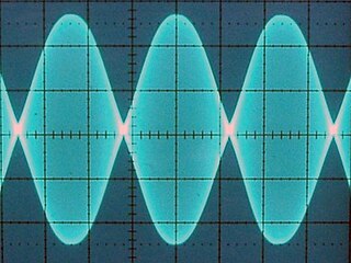
A linear amplifier is an electronic circuit whose output is proportional to its input, but capable of delivering more power into a load. The term usually refers to a type of radio-frequency (RF) power amplifier, some of which have output power measured in kilowatts, and are used in amateur radio. Other types of linear amplifier are used in audio and laboratory equipment. Linearity refers to the ability of the amplifier to produce signals that are accurate copies of the input. A linear amplifier responds to different frequency components independently, and tends not to generate harmonic distortion or intermodulation distortion. No amplifier can provide perfect linearity however, because the amplifying devices—transistors or vacuum tubes—follow nonlinear transfer function and rely on circuitry techniques to reduce those effects. There are a number of amplifier classes providing various trade-offs between implementation cost, efficiency, and signal accuracy.

<span class="mw-page-title-main">Thermal efficiency</span> Performance measure of a device that uses thermal energy

In thermodynamics, the thermal efficiency is a dimensionless performance measure of a device that uses thermal energy, such as an internal combustion engine, steam turbine, steam engine, boiler, furnace, refrigerator, ACs etc.
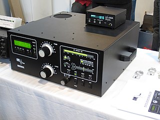
Technical specifications and detailed information on the valve audio amplifier, including its development history.

In electronics, power amplifier classes are letter symbols applied to different power amplifier types. The class gives a broad indication of an amplifier's characteristics and performance. The first three classes are related to the time period that the active amplifier device is passing current, expressed as a fraction of the period of a signal waveform applied to the input. This metric is known as conduction angle (θ). A class A amplifier is conducting through all the period of the signal (θ=360°); Class B only for one-half the input period (θ=180°), class C for much less than half the input period (θ<180°). Class D amplifiers operate their output device in a switching manner; the fraction of the time that the device is conducting may be adjusted so a pulse-width modulation output can be obtained from the stage.

References

  1. Anthony G. Atkins; Tony Atkins; Marcel Escudier (2013). A Dictionary of Mechanical Engineering. Oxford University Press. p. 269. ISBN   978-0-19-958743-8.
  2. Albert Thumann (2010). Plant Engineers and Managers Guide to Energy Conservation. The Fairmont Press, Inc. p. 320. ISBN   978-0-88173-657-1.
  3. William J. Eccles (2008). Pragmatic Power. Morgan & Claypool Publishers. p. 74. ISBN   978-1-59829-798-0.
  4. 1 2 3 Mukund R. Patel (2012). Introduction to Electrical Power and Power Electronics. CRC Press. pp. 54–55. ISBN   978-1-4665-5660-7.
  5. 1 2 Jerry C. Whitaker, ed. (2005). The Electronics Handbook, Second Edition. CRC Press. pp. 314–315. ISBN   978-1-4200-3666-4.
  6. 1 2 Gary Davis; Ralph Johnes (1989). The Sound Reinforcement Handbook (2nd ed.). Hal Leonard Corporation. p. 232. ISBN   978-1-61774-545-4.
  7. "IESO". Archived from the original on 2013-09-03.
  8. Danish proposal to a design CO2 index for new ships to the UN’s International Maritime Organization (IMO) from the Danish Maritime Authority [ permanent dead link ]
  9. John M. Seddon; Simon Newman (2011). Basic Helicopter Aerodynamics (3rd ed.). John Wiley & Sons. p. 231. ISBN   978-1-119-97272-3.
  10. Michael R. Lindeburg, PE (2013). Mechanical Engineering Reference Manual for the PE Exam. www.ppi2pass.com. pp. 72–. ISBN   978-1-59126-414-9.
  11. "Archived copy" (PDF). Archived from the original (PDF) on 2014-02-22. Retrieved 2014-02-11.{{cite web}}: CS1 maint: archived copy as title (link)
  12. Hamid A. Toliyat; Gerald B. Kliman (2004). Handbook of Electric Motors. CRC Press. p. 181. ISBN   978-0-8247-4105-1.
  13. Steve Senty (2012). Motor Control Fundamentals. Cengage Learning. p. 81. ISBN   978-1-133-70917-6.
  14. 1 2 3 Quilter, Patrick (2004). "How to Compare Amplifier Power Ratings." Archived 2010-01-11 at the Wayback Machine Sound and Song. Retrieveded on March 18, 2010.