STEP-NC interface on a CNC, showing product shape and color-coded tolerance state
STEP-NC is a machine tool control language that extends the ISO 10303 STEP standards with the machining model in ISO 14649,[1] adding geometric dimension and tolerance data for inspection, and the STEP PDM model for integration into the wider enterprise. The combined result has been standardized as ISO 10303-238[2] (also known as AP238).
A STEP-NC program can use the full range of geometric constructs[3] from the STEP standard to communicate device-independent toolpaths to the CNC. It can provide CAM operational descriptions and STEP CAD geometry to the CNC so workpieces, stock, fixtures and cutting tool shapes can be visualized and analyzed in the context of the toolpaths. STEP GD&T information can also be added to enable quality measurement on the control, and CAM-independent volume removal features[4] may be added to facilitate regeneration and modification of the toolpaths before or during machining for closed loop manufacturing.
Motivation
Impeller machined using STEP-NC
Input to a CNC in the ISO 6983/RS274D G-code control language is often machine-specific and limited to axis motion commands. The machine tool is given little or no information about the desired result of the machining.
STEP-NC allows more information about the machining process to be sent to the machine control and adds new information about the product being machined.[5] This "Smart Data for Smart Machining"[6] enables applications such as the following:
Toolpath descriptions that are portable and independent of machine geometry.[7]
Visual process, to show toolpaths in context of the machine and workpiece, and eliminate drawings.[8]
On-Machine Simulation, to check for gouges, machine interference and other undesired behavior.
Simplified Inspection, with linked tolerances, on-machine probes and inspection workplans tied to part tolerances.
Feed and Speed Optimization, using tolerances,[9] cross section information, sensor data.
Associativity so feedback can be sent from manufacturing back to design.
Capabilities
Overview of STEP-NC process model
STEP-NC can communicate a complete machining process description to a machine tool control or between manufacturing software applications. The information handled by STEP-NC can be divided into the following general categories. The standard handles technology-specific parameters for milling and turning, and extensions for other technologies under development (see Future work).
STEP-NC can exchange the explicit toolpath descriptions in use today, and add part, stock, and fixture geometry, a description of the tools, geometric dimensions and tolerances, and PDM information. A STEP-NC file is difficult to edit by hand because it contains geometry descriptions but for large programs the file size can be smaller because STEP-NC uses a compressedXML format instead of ASCII codes.
History
STEP-NC is not the first attempt at providing better quality information to a CNC. The EIA 494 Basic Control Language (BCL)[13] defined a control language that was portable and had toolpaths independent of machine geometry, but did not contain any of the other product model information found in STEP-NC.[14]
The core of STEP-NC is the ISO 14649 model for CNC control developed by European ESPRIT and IMS[15] STEP-NC projects begun in 1999. These were led by Siemens with contributions from RWTH Aachen University and the University of Stuttgart in Germany, Komatsu and FANUC in Japan, Heidenhain in Switzerland, and the Pohang University of Science and Technology in Korea.[16] Models for the control of CNC milling[11] and turning machines[12] were published in 2005, and draft models exist for EDM and contour cutting.
Integration of the CNC model into STEP[17] to produce ISO 10303-238 was done in the United States, under the NIST ATP Model Driven Intelligent Control of Manufacturing project, led by STEP Tools, Inc. with an industrial review board (IRB) consisting of Fortune 500 companies, CAD and CAM software developers, machine tool manufacturers, job shops and industry experts.[18] STEP-NC AP238 was published in 2007.[2]
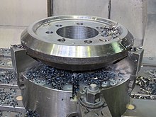
STEP-NC Crown Wheel
In 2005 the OMAC STEP-NC Working Group hosted an AP238 testing forum in Orlando to demonstrate 5-axis parts machined using AP238 CC1 machine independent toolpaths. Four CAD/CAM systems produced AP238 machining programs for milling a 5-axis test part (an NAS 979 circle/diamond/square with an inverted NAS 979 cone test in the center). Each run on a pair of CNCs configured for completely different machine geometries (AB tool tilt vs. BC table tilt).[19] In addition, Boeing cut parts on a variety of machines at their Tulsa facility and a machine at NIST in Gaithersburg.[20]
In June 2006, a live 5-axis STEP-NC machining demonstration was hosted by Airbus at the Université Paul Sabatier Laboratoire de Génie mécanique in Toulouse.[21] Further machining and measurement demonstrations were conducted in Ibusuki Japan in 2007.[22]
On March 10–12, 2008, the STEP Manufacturing team (ISO TC184 SC4 WG3 T24) met in Sandviken and Stockholm, Sweden to demonstrate use of STEP-NC for feed and speed optimization, high-speed machining, tolerance-driven tool compensation and traceability. The participants in the demonstrations included Airbus/Univ. Bordeaux, Boeing, Eurostep, KTH Royal Institute of Technology, NIST, Sandvik Coromant, Scania, STEP Tools, and Univ. of Vigo.[23]
On October 1–2, 2008, the STEP Manufacturing team met at the Connecticut Center for Advanced Technology, in Hartford, Connecticut to demonstrate closed-loop machining, feed optimization, and measurement using STEP-NC. The highlight of the meeting was the live 5-axis machining of a titanium impeller. Participants in the machining demonstration and other activities included Boeing, Connecticut Center for Advanced Technology, Concepts NRec, DMG, KTH Royal Institute of Technology, Mitutoyo, NIST, Sandvik Coromant, Scania, Siemens, and STEP Tools.[24]
These participants and others continue to hold STEP-NC international implementation and testing events on a roughly six-month cycle. The demonstrations in 2009 focused on machining a Mold part at multiple sites from the same AP238 data including one part machined on a FANUC-developed STEP-NC control. At a meeting in Seattle the parts were then measured for accuracy using a CMM probe and a laser scanner.[25]
STEP-NC machining on an Okuma CNC at IMTS 2014.
In the first half of 2010, the testing activity focused on tool wear management and machining a part in multiple setups with multiple alternate machining plans for 3, 4 and 5-axis machining. The new test part was a gear box that must be machined on all six sides. The tool wear and consequent machine loads were predicted from the STEP-NC data and verified using a dynamometer.[26] In the second half of 2010, the testing forum applied STEP-NC to set up compensation with on-machine measurement of part and fixture datums using a FaroArm portable measurement device.[27]
In 2012, the testing focused on machine tool accuracy calculations, culminating in a demonstration in June at the KTH production engineering labs in Stockholm. The test case milled a forged blank for a Crown Wheel Gear on an older Mazak VQC 20. Accuracy data from the machine was combined with tool engagement information from the STEP-NC to predict the deflections, which were tested against actual machining results.[28]
In 2014, CAM data exchange using STEP-NC was shown at IMTS 2014 with daily machining demonstrations hosted by Okuma. A base machining process for a mold part was created by Boeing and then sent to Sandvik and ISCAR for optimization, producing a STEP-NC description containing all three process options. All machining was done in titanium and a range of CAM software was used, with all results captured as STEP-NC.[29][30]
At IMTS 2018, a team consisting of Airbus, Boeing, DMG MORI, Hyundai WIA, Renishaw, and Mitutoyo demonstrated Digital Twin manufacturing by combining STEP-NC model and process data with MTConnect machine tool status and Quality Information Format (QIF) metrology results.[31]
A second edition of AP238 was published in 2020,[32] followed by a third edition in 2022[33] for model-based integrated manufacturing, with geometry, tolerance, and kinematics improvements first introduced by AP242.
Future work
STEP-NC plasma cutting
Work continues within the ISO standard committees to extend STEP-NC to new technologies and to incorporate refinements discovered during use. Process models for new technologies are usually produced by the ISO TC184/SC1/WG7 committee. Models for Wire & Sink EDM[34] and contour cutting of wood or stone are under investigation.
Work on extending and integrating STEP-NC with the manufacturing enterprise takes place in the ISO TC184/SC4/WG3/T24 STEP Manufacturing Team.[35] This group also works on extensions and refinements discovered during testing. A series of traceability extensions have been proposed for linking STEP-NC machining programs with sensor feedback and machine state information during execution.[36]
The National Shipbuilding Research Program (NSRP) has also hosted work to implement a prototype that connects a shipyard design system to a plate cutting using STEP-NC.[37] This work involved extending STEP-NC to steel plate cutting and marking using lasers and plasma torches.
Related Research Articles
Computer-aided manufacturing (CAM) also known as computer-aided modeling or computer-aided machining is the use of software to control machine tools in the manufacturing of work pieces. This is not the only definition for CAM, but it is the most common. It may also refer to the use of a computer to assist in all operations of a manufacturing plant, including planning, management, transportation and storage. Its primary purpose is to create a faster production process and components and tooling with more precise dimensions and material consistency, which in some cases, uses only the required amount of raw material, while simultaneously reducing energy consumption. CAM is now a system used in schools and lower educational purposes. CAM is a subsequent computer-aided process after computer-aided design (CAD) and sometimes computer-aided engineering (CAE), as the model generated in CAD and verified in CAE can be input into CAM software, which then controls the machine tool. CAM is used in many schools alongside CAD to create objects.
A machine tool is a machine for handling or machining metal or other rigid materials, usually by cutting, boring, grinding, shearing, or other forms of deformations. Machine tools employ some sort of tool that does the cutting or shaping. All machine tools have some means of constraining the workpiece and provide a guided movement of the parts of the machine. Thus, the relative movement between the workpiece and the cutting tool is controlled or constrained by the machine to at least some extent, rather than being entirely "offhand" or "freehand". It is a power-driven metal cutting machine which assists in managing the needed relative motion between cutting tool and the job that changes the size and shape of the job material.
Geometric dimensioning and tolerancing (GD&T) is a system for defining and communicating engineering tolerances via a symbolic language on engineering drawings and computer-generated 3D models that describes a physical object's nominal geometry and the permissible variation thereof. GD&T is used to define the nominal geometry of parts and assemblies, the allowable variation in size, form, orientation, and location of individual features, and how features may vary in relation to one another such that a component is considered satisfactory for its intended use. Dimensional specifications define the nominal, as-modeled or as-intended geometry, while tolerance specifications define the allowable physical variation of individual features of a part or assembly.
G-code is the most widely used computer numerical control (CNC) and 3D printing programming language. It is used mainly in computer-aided manufacturing to control automated machine tools, as well as for 3D-printer slicer applications. The G stands for geometry. G-code has many variants.
The Initial Graphics Exchange Specification (IGES) is a vendor-neutral file format that allows the digital exchange of information among computer-aided design (CAD) systems. It's an ASCII-based textual format.
ISO 10303 is an ISO standard for the computer-interpretable representation and exchange of product manufacturing information. It is an ASCII-based format. Its official title is: Automation systems and integration — Product data representation and exchange. It is known informally as "STEP", which stands for "Standard for the Exchange of Product model data". ISO 10303 can represent 3D objects in Computer-aided design (CAD) and related information.
STEP-file is a widely used data exchange form of STEP. ISO 10303 can represent 3D objects in computer-aided design (CAD) and related information. Due to its ASCII structure, a STEP-file is easy to read, with typically one instance per line. The format of a STEP-file is defined in ISO 10303-21 Clear Text Encoding of the Exchange Structure.
In solid modeling and computer-aided design, boundary representation is a method for representing a 3D shape by defining the limits of its volume. A solid is represented as a collection of connected surface elements, which define the boundary between interior and exterior points.
Tebis is a CAD/CAM software provided by Tebis AG, with headquarters in Martinsried near Munich/Germany. Development locations: Martinsried and Norderstedt, Germany International locations: China, Spain, France, Italy, Portugal, Sweden, United Kingdom, USA.
ISO 10303-22 is a part of the implementation methods of STEP with the official title Standard data access interface or simply SDAI.
Manufacturing Message Specification (MMS) is an international standard dealing with messaging systems for transferring real time process data and supervisory control information between networked devices or computer applications. The standard is developed and maintained by the ISO Technical Committee 184 (TC184). MMS defines the following
Product and manufacturing information, also abbreviated PMI, conveys non-geometric attributes in 3D computer-aided design (CAD) and Collaborative Product Development systems necessary for manufacturing product components and assemblies. PMI may include geometric dimensions and tolerances, 3D annotation (text) and dimensions, surface finish, and material specifications. PMI is used in conjunction with the 3D model within model-based definition to allow for the elimination of 2D drawings for data set utilization.
CAD data exchange is a method of drawing data exchange used to translate between different computer-aided design (CAD) authoring systems or between CAD and other downstream CAx systems.
EXPRESS is a standard for generic data modeling language for product data. EXPRESS is formalized in the ISO Standard for the Exchange of Product model STEP, and standardized as ISO 10303-11.
James G. "Jim" Nell is an American engineer. He was the principal investigator of the Manufacturing Enterprise Integration Project at the National Institute of Standards and Technology (NIST), and is known for his work on enterprise integration.
ISO/TC 184/SC 4 is an international standards organization responsible for industrial data. ISO/TC 184/SC 4 develops and maintains ISO standards that describe and manage industrial product data throughout the life of the product. ISO/TC 184/SC 4, Industrial data, is Subcommittee 4 of ISO/TC 184, Automation systems and integration, which is Technical Committee 184 of the International Organization for Standardization (ISO).
WorkNC is a Computer aided manufacturing (CAM) software developed by Sescoi for multi-axis machining.
LinuxCNC is a free, open-source Linux software system that implements numerical control capability using general purpose computers to control CNC machines. It's mainly intended to run on PC AMD x86-64 systems. Designed by various volunteer developers at linuxcnc.org, it is typically bundled as an ISO file with a modified version of Debian Linux which provides the required real-time kernel.
Tool management is needed in metalworking so that the information regarding the tools on hand can be uniformly organized and integrated. The information is stored in a database and is registered and applied using tool management. Tool data management consists of specific data fields, graphics and parameters that are essential in production, as opposed to managing general production equipment.
The history of numerical control (NC) began when the automation of machine tools first incorporated concepts of abstractly programmable logic, and it continues today with the ongoing evolution of computer numerical control (CNC) technology.
↑ Xu, X; Klemm, P; Proctor, F; Suh., S. H. (September 2006). "STEP Compliant Process Planning and Manufacturing". International Journal of Computer Integrated Manufacturing. 19 (6): 491–494. doi:10.1080/09511920600669776. S2CID40205026.
↑ Hardwick, M.; Loffredo, D. (March 2007). "STEP-NC: Smart Data for Smart Machining". Proceedings of the Intl. Conf. on Smart Machining Systems. Intl. Conf. on Smart Machining Systems. NIST, Gaithersburg, MD.
↑ Kennedy, Bill (July 2007). "All Together Now: STEP-NC"(PDF). Cutting Tool Engineering. 59 (7). Retrieved 2008-10-27.
↑ ANSI/EIA-494-B-1992 (1992). 32-Bit Binary CL (BCL) and 7-Bit ASCII CL (ACL) Exchange Input Format for Numerically Controlled Machines. Washington, D.C: Electronic Industries Association.
↑ Hardwick, M.; Loffredo, D. (September 2007). "Challenges and Choices in the Specification and Implementation of the STEP-NC AP-238 Standard". Journal of Computing and Information Science in Engineering. 7 (3): 283–291. doi:10.1115/1.2768090.
↑ Suh, S. H.; Cho, J. H.; Hong, H. D. (January 2002). "On the architecture of intelligent STEP-compliant CNC". International Journal of Computer Integrated Manufacturing. 15 (2): 168–177. doi:10.1080/09511920110056541. S2CID205627568.
↑ Lorincz, Jim (September 2015). "Optimize Process for Best Performance". Advanced Manufacturing: Aerospace and Defense Manufacturing 2015. SME. Retrieved 2015-11-17.
↑ Sokolov, A.; Richard, J.; Nguyen, V. K.; Stroud, I.; Maeder, W.; Xirouchakis, P. (September 2006). "Algorithms and an extended STEP-NC-compliant data model for wire electro discharge machining based on 3D representations". International Journal of Computer Integrated Manufacturing. 19 (6): 603–613. doi:10.1080/09511920600634903. S2CID43244191.
↑ Garrido Campos, J.; Hardwick, M. (2006). "A Traceability Information Model for CNC Manufacturing". Computer-Aided Design. 38 (5): 540–551. doi:10.1016/j.cad.2006.01.011.
This page is based on this Wikipedia article Text is available under the CC BY-SA 4.0 license; additional terms may apply. Images, videos and audio are available under their respective licenses.