Contact protection

Last updated

Contact protection methods are designed to mitigate the wear and degradation occurring during the normal use of contacts within an electromechanical switch, relay or contactor and thus avoid an excessive increase in contact resistance or switch failure.

Contents

Contact wear

Typical contact elements of an electromechanical relay or contactor. M-Electrode Pic.jpg
Typical contact elements of an electromechanical relay or contactor.

A “contact” is a pair of electrodes (typically, one moving; one stationary) designed to control electricity. Electromechanical switches, relays, and contactors “turn power on” when the moving electrode makes contact with the stationary electrode to carry current. Conversely, they “turn power off” when the moving electrode breaks contact and the resulting arc plasma stops burning as the dielectric gap widens sufficiently to prevent current flow. Power relays and contactors have two primary life expectancy ratings: “mechanical life” is based on operating either without current or below the wetting current (i.e., “Dry”) and “electrical life” is based on operating above the wetting current (i.e., “Wet”). These different ratings are due to contacts being designed to compensate for the destructive arcing that naturally occurs between the electrodes during normal Wet operation. Contact arcing is so destructive that the electrical life of power relays and contactors is most often a fraction of their respective mechanical life. [1] [2]

From left to right:
Pristine contacts from a relay
The nearly destroyed contacts from a relay operated under power for nearly 100,000 cycles Contacts - new and used.jpg
From left to right:
  1. Pristine contacts from a relay
  2. The nearly destroyed contacts from a relay operated under power for nearly 100,000 cycles

Every time the contacts of an electromechanical switch, relay or contactor are opened or closed, there is a certain amount of contact wear. If the contact is cycling without electricity (dry), the impact of the contact electrodes a slightly deformed by the resulting cold forging. [1] When the contact is operating under power (wet), the sources of the wear are the result of high current densities in microscopic areas, and the electric arc. [2] Contact wear includes material transfer between contacts, loss of contact material due to splattering and evaporation, and oxidation or corrosion of the contacts due to high temperatures and atmospheric influences. [3] [4]

While a pair of contacts is closed, only a small part of the contacts are in intimate contact due to asperities and low-conductivity films. Because of the constriction of the current to a very small area, the current density frequently becomes so high that it melts a microscopic portion of the contact. [5] During the close-to-open (BREAK) transition, a microscopic molten bridge forms and eventually ruptures asymmetrically, transferring contact material between contacts and increasing the surface roughness. This can also occur during the open-to-close (MAKE) transition due to contact bounce.

The electric arc occurs between the contact points (electrodes) both during the transition from closed to open (BREAK) and from open to closed (make) when the contact gap is small and the voltage is high enough. Heating due to arcing and high current density can melt the contact surface temporarily. If some of the melting material solidifies while the contacts are closed, the contact may stick closed due to a micro-weld, similar to spot welding. [2]

The arc caused during the contact BREAK (BREAK arc) is similar to arc welding, as the BREAK arc is typically more energetic and more destructive. [6] The arc can cause material transfer between contacts. [7] The arc may also be hot enough to evaporate metal from the contact surface.

The high temperatures can also cause the contact metals to more rapidly oxidize and corrode.

Contacts reach end of life for one of two reasons. Either the contacts fail to BREAK because they are stuck (welded) closed, or the contacts fail to make (high resistance) because of contact corrosion or because excessive material is lost from one or both contacts. These conditions are the result of cumulative material transfer during successive switching operations, and of material loss due to evaporation and splattering. [8]

There are additional mechanisms for stuck closed failures, such as mechanical interlocking of rough contact surfaces due to contact wear.

Protection

Contact Protection Using Electronic Power Contact Arc Suppression - from left to right: new contact (out of box); failed contact with < 100K unprotected cycles; "like new" contact after 100K protected cycles; and "like new" contact after 1 million protected cycles. Relay Life Unsuppressed vs Suppressed Arcing.jpg
Contact Protection Using Electronic Power Contact Arc Suppression - from left to right: new contact (out of box); failed contact with < 100K unprotected cycles; "like new" contact after 100K protected cycles; and "like new" contact after 1 million protected cycles.

The degradation of the contacts can be limited by including various contact protection methods.

Below 2 Amperes, a variety of transient suppressing electronic components have been employed with varying success as arc suppressors, including: capacitors, snubbers, diodes, Zener diodes, transient voltage suppressors (TVS), resistors, varistors or in-rush current limiters (PTC and NTC resistors). [9] However, this is the least effective method as these neither significantly influence the creation of nor suppress the arc between the contacts of electromechanical power switches, relays and contactors. [10] [11] [12]

Historically, the two most common approaches to contact protection (above 2 Amperes) have been making the contacts themselves larger, i.e., a contactor [13] and/or making the contacts out of more durable metals or metal alloys such as tungsten. [8]

The most effective methods are to employ arc suppression circuitry including electronic power contact arc suppressors, solid state relays, hybrid power relays, mercury displacement relays and hybrid power contactors. [14] [15] [16] [17] [18]

See also

Related Research Articles

<span class="mw-page-title-main">Relay</span> Electrically-operated switch

A relay is an electrically operated switch. It consists of a set of input terminals for a single or multiple control signals, and a set of operating contact terminals. The switch may have any number of contacts in multiple contact forms, such as make contacts, break contacts, or combinations thereof.

In electrical engineering, a switch is an electrical component that can disconnect or connect the conducting path in an electrical circuit, interrupting the electric current or diverting it from one conductor to another. The most common type of switch is an electromechanical device consisting of one or more sets of movable electrical contacts connected to external circuits. When a pair of contacts is touching current can pass between them, while when the contacts are separated no current can flow.

<span class="mw-page-title-main">Spot welding</span> Process in which contacting metal surfaces are joined by heat from resistance to electric current

Spot welding is a type of electric resistance welding used to weld various sheet metal products, through a process in which contacting metal surface points are joined by the heat obtained from resistance to electric current.

<span class="mw-page-title-main">Shielded metal arc welding</span> Manual arc welding process

Shielded metal arc welding (SMAW), also known as manual metal arc welding, flux shielded arc welding or informally as stick welding, is a manual arc welding process that uses a consumable electrode covered with a flux to lay the weld.

<span class="mw-page-title-main">Submerged arc welding</span> Joining metals using electricity, beneath a granulated flux material

Submerged arc welding (SAW) is a common arc welding process. The first SAW patent was taken out in 1935. The process requires a continuously fed consumable solid or tubular electrode. The molten weld and the arc zone are protected from atmospheric contamination by being "submerged" under a blanket of granular fusible flux consisting of lime, silica, manganese oxide, calcium fluoride, and other compounds. When molten, the flux becomes conductive, and provides a current path between the electrode and the work. This thick layer of flux completely covers the molten metal thus preventing spatter and sparks as well as suppressing the intense ultraviolet radiation and fumes that are a part of the shielded metal arc welding (SMAW) process.

<span class="mw-page-title-main">Mercury switch</span> Type of electrical switch

A mercury switch is an electrical switch that opens and closes a circuit when a small amount of the liquid metal mercury connects metal electrodes to close the circuit. There are several different basic designs but they all share the common design strength of non-eroding switch contacts.

<span class="mw-page-title-main">Reed switch</span> Electrical switch operated by an applied magnetic field

The reed switch is an electromechanical switch operated by an applied magnetic field. It was invented in 1922 by professor Valentin Kovalenkov at the Petrograd Electrotechnical University, and later evolved at Bell Telephone Laboratories in 1936 by Walter B. Ellwood into the reed relay. In its simplest and most common form, it consists of a pair of ferromagnetic flexible metal contacts in a hermetically sealed glass envelope. The contacts are usually normally open, closing when a magnetic field is present, or they may be normally closed and open when a magnetic field is applied. The switch may be actuated by an electromagnetic coil, making a reed relay, or by bringing a permanent magnet near it. When the magnetic field is removed, the contacts in the reed switch return to their original position. The "reed" is the metal part inside the reed switch envelope that is relatively thin and wide to make it flexible. It somewhat resembles part of some reed plants. The term "reed" may also include the external wire lead as well as the internal part.

A snubber is a device used to suppress a phenomenon such as voltage transients in electrical systems, pressure transients in fluid systems or excess force or rapid movement in mechanical systems.

<span class="mw-page-title-main">Plasma cutting</span> Process

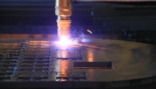
Plasma cutting is a process that cuts through electrically conductive materials by means of an accelerated jet of hot plasma. Typical materials cut with a plasma torch include steel, stainless steel, aluminum, brass and copper, although other conductive metals may be cut as well. Plasma cutting is often used in fabrication shops, automotive repair and restoration, industrial construction, and salvage and scrapping operations. Due to the high speed and precision cuts combined with low cost, plasma cutting sees widespread use from large-scale industrial computer numerical control (CNC) applications down to small hobbyist shops.

<span class="mw-page-title-main">Electric arc</span> Electrical breakdown of a gas that results in an ongoing electrical discharge

An electric arc is an electrical breakdown of a gas that produces a prolonged electrical discharge. The current through a normally nonconductive medium such as air produces a plasma, which may produce visible light. An arc discharge is initiated either by thermionic emission or by field emission. After initiation, the arc relies on thermionic emission of electrons from the electrodes supporting the arc. An arc discharge is characterized by a lower voltage than a glow discharge. An archaic term is voltaic arc, as used in the phrase "voltaic arc lamp".

<span class="mw-page-title-main">Electrical contact</span> Electrical circuit component

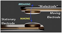
An electrical contact is an electrical circuit component found in electrical switches, relays, connectors and circuit breakers. Each contact is a piece of electrically conductive material, typically metal. When a pair of contacts touch, they can pass an electrical current with a certain contact resistance, dependent on surface structure, surface chemistry and contact time; when the pair is separated by an insulating gap, then the pair does not pass a current. When the contacts touch, the switch is closed; when the contacts are separated, the switch is open. The gap must be an insulating medium, such as air, vacuum, oil, SF6. Contacts may be operated by humans in push-buttons and switches, by mechanical pressure in sensors or machine cams, and electromechanically in relays. The surfaces where contacts touch are usually composed of metals such as silver or gold alloys that have high electrical conductivity, wear resistance, oxidation resistance and other properties.

<span class="mw-page-title-main">Gas tungsten arc welding</span> Welding process

Gas tungsten arc welding (GTAW), also known as tungsten inert gas (TIG) welding, is an arc welding process that uses a non-consumable tungsten electrode to produce the weld. The weld area and electrode are protected from oxidation or other atmospheric contamination by an inert shielding gas. A filler metal is normally used, though some welds, known as autogenous welds, or fusion welds do not require it. When helium is used, this is known as heliarc welding. A constant-current welding power supply produces electrical energy, which is conducted across the arc through a column of highly ionized gas and metal vapors known as a plasma.
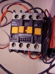
 TIG welding is most commonly used to weld thin sections of stainless steel and non-ferrous metals such as aluminum, magnesium, and copper alloys. The process grants the operator greater control over the weld than competing processes such as shielded metal arc welding and gas metal arc welding, allowing stronger, higher-quality welds. However, TIG welding is comparatively more complex and difficult to master, and furthermore, it is significantly slower than most other welding techniques. A related process, plasma arc welding, uses a slightly different welding torch to create a more focused welding arc and as a result is often automated.

<span class="mw-page-title-main">Contactor</span> Electronic circuit element serving as a switch

A contactor is an electrically-controlled switch used for switching an electrical power circuit. A contactor is typically controlled by a circuit which has a much lower power level than the switched circuit, such as a 24-volt coil electromagnet controlling a 230-volt motor switch.

<span class="mw-page-title-main">Solid-state relay</span> Electronic switching device responding to external voltage

A solid state relay (SSR) is an electronic switching device that switches on or off when an external voltage is applied across its control terminals. They serve the same function as an electromechanical relay, but solid-state electronics contain no moving parts and have a longer operational lifetime. Solid state relays were invented in 1971 by the Crydom Controls division of International Rectifiers. After a number of corporate acquisitions, Crydom is now part of Sensata.

<span class="mw-page-title-main">Hyperbaric welding</span> Welding metal at elevated pressure

Hyperbaric welding is the process of welding at elevated pressures, normally underwater. Hyperbaric welding can either take place wet in the water itself or dry inside a specially constructed positive pressure enclosure and hence a dry environment. It is predominantly referred to as "hyperbaric welding" when used in a dry environment, and "underwater welding" when in a wet environment. The applications of hyperbaric welding are diverse—it is often used to repair ships, offshore oil platforms, and pipelines. Steel is the most common material welded.

<span class="mw-page-title-main">Failure of electronic components</span> Ways electronic components fail and prevention measures

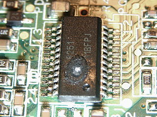
Electronic components have a wide range of failure modes. These can be classified in various ways, such as by time or cause. Failures can be caused by excess temperature, excess current or voltage, ionizing radiation, mechanical shock, stress or impact, and many other causes. In semiconductor devices, problems in the device package may cause failures due to contamination, mechanical stress of the device, or open or short circuits.

Automatic test system switching test equipment allows for high-speed testing of a device or devices in a test situation, where strict sequences and combinations of switching must be observed. By automating the process in this way, the possibility of test errors and inaccuracies is minimized, and only systematic errors would generally be encountered due to such as an incorrect programmed test condition. This eliminates error due to human factors and allows application of a standard test sequence repetitively. The design of a test system’s switching configuration is governed by the test specification, which is derived from the functional tests to be performed.

Arc suppression is the reduction of the electric arc energy that occurs when current-carrying contacts are opened and closed. An electric arc is a man-made, continuous arc-discharge comprised of highly energized electrons and ions supported by an electric current of at least 100mA; not to be confused with an electric spark.

<span class="mw-page-title-main">Gas metal arc welding</span> Industrial welding process

Gas metal arc welding (GMAW), sometimes referred to by its subtypes metal inert gas (MIG) and metal active gas (MAG) is a welding process in which an electric arc forms between a consumable MIG wire electrode and the workpiece metal(s), which heats the workpiece metal(s), causing them to fuse. Along with the wire electrode, a shielding gas feeds through the welding gun, which shields the process from atmospheric contamination.

<span class="mw-page-title-main">Vacuum interrupter</span>

In electrical engineering, a vacuum interrupter is a switch which uses electrical contacts in a vacuum. It is the core component of medium-voltage circuit-breakers, generator circuit-breakers, and high-voltage circuit-breakers. Separation of the electrical contacts results in a metal vapour arc, which is quickly extinguished. Vacuum interrupters are widely used in utility power transmission systems, power generation unit, and power-distribution systems for railways, arc furnace applications, and industrial plants.

References

  1. 1 2 Thorbus, Robert; Henke, Reinhold (2021-01-01). "THE DRY POWER CONTACT CYCLE; Contact Activity Without Arc-Supporting Current". AST Academic Poster #8 of 16.
  2. 1 2 3 Thorbus, Robert; Henke, Reinhold (2021-01-01). "THE WET POWER CONTACT CYCLE; Contact Activity With Arc-Supporting Current". AST Academic Poster #9 of 16.
  3. Thorbus, Robert; Henke, Reinhold (2021-01-01). "RETHINKING CONTACT CURRENT ARCING; Insights into an Old Chronic Problem". AST Academic Poster #1 of 16.
  4. Thorbus, Robert; Henke, Reinhold (2021-01-01). "THE ARC SPECIES ZOO; Arcs Are Self-feeding Plasma Burning Monsters; Sparks Are Not". AST Academic Poster #4 of 16.
  5. Stress-Dependent Electrical Contact Resistance at Fractal Rough Surfaces Journal of Engineering Mechanics 143
  6. Holm, Ragnar (1958). Electric Contacts Handbook (3rd ed.). Springer-Verlag, Berlin / Göttingen / Heidelberg. pp. 331–342.
  7. "Troubleshooting Common Electrical Contact Problems". PEP Brainin. 2013-12-13. Retrieved 2017-03-05.
  8. 1 2 "Relay Contact Life" . Retrieved January 21, 2018.
  9. Tyco P&B, Relay Contact Life, Tyco Electronics Corporation – P&B, Winston-Salem, NC, Application Note 13C3236, pgs. 1-3
  10. "The Snubber Myth". Archived from the original on December 4, 2013. Retrieved February 10, 2012.
  11. Thorbus, Robert; Henke, Reinhold (2021-01-01). "WHAT IS ARC SUPPRESSION? Three Historical Interpretations and Our Findings". AST Academic Poster #5 of 16.
  12. Henke, Reinhold; Thorbus, Robert. "FACTS & MYTHS OF ARC SUPPRESSION; Bringing Clarity to Address the Uncertainty and Confusion". www.academia.edu. Retrieved 2023-06-21.
  13. Terrell Croft and Wilford Summers (ed), American Electricans' Handbook, Eleventh Edition, McGraw Hill, New York (1987) ISBN   0-07-013932-6 page 7-124
  14. Thorbus, Robert; Henke, Reinhold (2021-01-01). "THE EPCAS CYCLE; Contact Activity With Electronic Power Contact Arc Suppression". AST Academic Poster #10 of 16.
  15. "Current solutions". Archived from the original on December 4, 2013. Retrieved February 10, 2012.
  16. The National Association of Relay Manufacturers, Engineers’ Relay Handbook, NARM, 8th Edition, 1980, Chapter 13
  17. Reference Patent Application Publication # 20080266742 assigned to Watlow Electric Manufacturing Company
  18. "Arc Suppression" . Retrieved December 6, 2013.