In telecommunication, the free-space path loss (FSPL) is the attenuation of radio energy between the feedpoints of two antennas that results from the combination of the receiving antenna's capture area plus the obstacle-free, line-of-sight path through free space. The "Standard Definitions of Terms for Antennas", IEEE Std 145-1993, defines "free-space loss" as "The loss between two isotropic radiators in free space, expressed as a power ratio." It does not include any power loss in the antennas themselves due to imperfections such as resistance. Free space loss increases with the square of distance between the antennas because the radio waves spread out by the inverse square law and decreases with the square of the wavelength of the radio waves. The FSPL is rarely used standalone, but rather as a part of the Friis transmission formula, which includes the gain of antennas. It is a factor that must be included in the power link budget of a radio communication system, to ensure that sufficient radio power reaches the receiver such that the transmitted signal is received intelligibly.
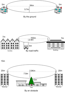
A Fresnel zone, named after physicist Augustin-Jean Fresnel, is one of a series of confocal prolate ellipsoidal regions of space between and around a transmitter and a receiver. The primary wave will travel in a relative straight line from the transmitter to the receiver. Aberrant transmitted radio, sound, or light waves which are transmitted at the same time can follow slightly different paths before reaching a receiver, especially if there are obstructions or deflecting objects between the two. The two waves can arrive at the receiver at slightly different times and the aberrant wave may arrive out of phase with the primary wave due to the different path lengths. Depending on the magnitude of the phase shift relative to the two waves, the waves can interfere constructively or destructively. The size of the calculated Fresnel zone at any particular distance from the transmitter and receiver can help to predict whether obstructions or discontinuities along the path will cause significant interference.
Path loss, or path attenuation, is the reduction in power density (attenuation) of an electromagnetic wave as it propagates through space. Path loss is a major component in the analysis and design of the link budget of a telecommunication system.

Line-of-sight propagation is a characteristic of electromagnetic radiation or acoustic wave propagation which means waves travel in a direct path from the source to the receiver. Electromagnetic transmission includes light emissions traveling in a straight line. The rays or waves may be diffracted, refracted, reflected, or absorbed by the atmosphere and obstructions with material and generally cannot travel over the horizon or behind obstacles.

Radio propagation is the behavior of radio waves as they travel, or are propagated, from one point to another, or into various parts of the atmosphere. As a form of electromagnetic radiation, like light waves, radio waves are affected by the phenomena of reflection, refraction, diffraction, absorption, polarization, and scattering. Understanding the effects of varying conditions on radio propagation has many practical applications, from choosing frequencies for international shortwave broadcasters, to designing reliable mobile telephone systems, to radio navigation, to operation of radar systems.
In optics, the Fraunhofer diffraction equation is used to model the diffraction of waves when the diffraction pattern is viewed at a long distance from the diffracting object, and also when it is viewed at the focal plane of an imaging lens. In contrast, the diffraction pattern created near the object is given by the Fresnel diffraction equation.
Non-line-of-sight (NLOS) radio propagation occurs outside of the typical line of sight (LOS) between the transmitter and receiver, such as in ground reflections. Near-line-of-sight conditions refer to partial obstruction by a physical object present in the innermost Fresnel zone.
In optics, the Fresnel diffraction equation for near-field diffraction is an approximation of the Kirchhoff–Fresnel diffraction that can be applied to the propagation of waves in the near field. It is used to calculate the diffraction pattern created by waves passing through an aperture or around an object, when viewed from relatively close to the object. In contrast the diffraction pattern in the far field region is given by the Fraunhofer diffraction equation.

The Fresnel number (F), named after the physicist Augustin-Jean Fresnel, is a dimensionless number occurring in optics, in particular in scalar diffraction theory.
Weissberger’s modified exponential decay model, or simply, Weissberger’s model, is a radio wave propagation model that estimates the path loss due to the presence of one or more trees in a point-to-point telecommunication link. This model belongs to the category Foliage or Vegetation models.
The ITU vegetation model is a radio propagation model that estimates the path loss encountered due to the presence of one or more trees inside a point to point telecommunication link. The predictions found from this model is congruent to those found from Weissberger’s modified exponential decay model in low frequencies.
The Egli model is a terrain model for radio frequency propagation. This model, which was first introduced by John Egli in his 1957 paper, was derived from real-world data on UHF and VHF television transmissions in several large cities. It predicts the total path loss for a point-to-point link. Typically used for outdoor line-of-sight transmission, this model provides the path loss as a single quantity.
The Lee model for area-to-area mode is a radio propagation model that operates around 900 MHz. Built as two different modes, this model includes an adjustment factor that can be adjusted to make the model more flexible to different regions of propagation.
The ITU Single Vegetative Obstruction Model is a Radio propagation model that quantitatively approximates the attenuation due to the vegetation in the middle of a telecommunication link.
The Okumura model is a radio propagation model that was built using the data collected in the city of Tokyo, Japan. The model is ideal for using in cities with many urban structures but not many tall blocking structures. The model served as a base for the Hata model.
The Lee model for point-to-point mode is a radio propagation model that operates around 900 MHz. Built as two different modes, this model includes an adjustment factor that can be adjusted to make the model more flexible to different regions of propagation.
The log-distance path loss model is a radio propagation model that predicts the path loss a signal encounters inside a building or densely populated areas over distance.
The Hata model is a radio propagation model for predicting the path loss of cellular transmissions in exterior environments, valid for microwave frequencies from 150 to 1500 MHz. It is an empirical formulation based on the data from the Okumura model, and is thus also commonly referred to as the Okumura–Hata model. The model incorporates the graphical information from Okumura model and develops it further to realize the effects of diffraction, reflection and scattering caused by city structures. Additionally, the Hata Model applies corrections for applications in suburban and rural environments.
Diffraction processes affecting waves are amenable to quantitative description and analysis. Such treatments are applied to a wave passing through one or more slits whose width is specified as a proportion of the wavelength. Numerical approximations may be used, including the Fresnel and Fraunhofer approximations.

The two-rays ground-reflection model is a multipath radio propagation model which predicts the path losses between a transmitting antenna and a receiving antenna when they are in line of sight (LOS). Generally, the two antenna each have different height. The received signal having two components, the LOS component and the reflection component formed predominantly by a single ground reflected wave.


