The wave impedance of an electromagnetic wave is the ratio of the transverse components of the electric and magnetic fields. For a transverse-electric-magnetic (TEM) plane wave traveling through a homogeneous medium, the wave impedance is everywhere equal to the intrinsic impedance of the medium. In particular, for a plane wave travelling through empty space, the wave impedance is equal to the impedance of free space. The symbol Z is used to represent it and it is expressed in units of ohms. The symbol η (eta) may be used instead of Z for wave impedance to avoid confusion with electrical impedance.

Coaxial cable, or coax, is a type of electrical cable consisting of an inner conductor surrounded by a concentric conducting shield, with the two separated by a dielectric ; many coaxial cables also have a protective outer sheath or jacket. The term coaxial refers to the inner conductor and the outer shield sharing a geometric axis.

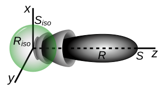
In electromagnetics, an antenna's gain is a key performance parameter which combines the antenna's directivity and radiation efficiency. The term power gain has been deprecated by IEEE. In a transmitting antenna, the gain describes how well the antenna converts input power into radio waves headed in a specified direction. In a receiving antenna, the gain describes how well the antenna converts radio waves arriving from a specified direction into electrical power. When no direction is specified, gain is understood to refer to the peak value of the gain, the gain in the direction of the antenna's main lobe. A plot of the gain as a function of direction is called the antenna pattern or radiation pattern. It is not to be confused with directivity, which does not take an antenna's radiation efficiency into account.

The near field and far field are regions of the electromagnetic (EM) field around an object, such as a transmitting antenna, or the result of radiation scattering off an object. Non-radiative near-field behaviors dominate close to the antenna or scatterer, while electromagnetic radiation far-field behaviors predominate at greater distances.

Effective radiated power (ERP), synonymous with equivalent radiated power, is an IEEE standardized definition of directional radio frequency (RF) power, such as that emitted by a radio transmitter. It is the total power in watts that would have to be radiated by a half-wave dipole antenna to give the same radiation intensity as the actual source antenna at a distant receiver located in the direction of the antenna's strongest beam. ERP measures the combination of the power emitted by the transmitter and the ability of the antenna to direct that power in a given direction. It is equal to the input power to the antenna multiplied by the gain of the antenna. It is used in electronics and telecommunications, particularly in broadcasting to quantify the apparent power of a broadcasting station experienced by listeners in its reception area.

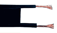
Twin-lead cable is a two-conductor flat cable used as a balanced transmission line to carry radio frequency (RF) signals. It is constructed of two stranded or solid copper or copper-clad steel wires, held a precise distance apart by a plastic ribbon. The uniform spacing of the wires is the key to the cable's function as a transmission line; any abrupt changes in spacing would reflect some of the signal back toward the source. The plastic also covers and insulates the wires. It is available with several different values of characteristic impedance, the most common type is 300 ohm.

In radio and telecommunications a dipole antenna or doublet is one of the two simplest and most widely-used types of antenna; the other is the monopole. The dipole is any one of a class of antennas producing a radiation pattern approximating that of an elementary electric dipole with a radiating structure supporting a line current so energized that the current has only one node at each far end. A dipole antenna commonly consists of two identical conductive elements such as metal wires or rods. The driving current from the transmitter is applied, or for receiving antennas the output signal to the receiver is taken, between the two halves of the antenna. Each side of the feedline to the transmitter or receiver is connected to one of the conductors. This contrasts with a monopole antenna, which consists of a single rod or conductor with one side of the feedline connected to it, and the other side connected to some type of ground. A common example of a dipole is the "rabbit ears" television antenna found on broadcast television sets. All dipoles are electrically equivalent to two monopoles mounted end-to-end and fed with opposite phases, with the ground plane between them made "virtual" by the opposing monopole.
In number theory, a Heegner number is a square-free positive integer d such that the imaginary quadratic field has class number 1. Equivalently, the ring of algebraic integers of has unique factorization.
In telecommunications, particularly in radio frequency engineering, signal strength refers to the transmitter power output as received by a reference antenna at a distance from the transmitting antenna. High-powered transmissions, such as those used in broadcasting, are expressed in dB-millivolts per metre (dBmV/m). For very low-power systems, such as mobile phones, signal strength is usually expressed in dB-microvolts per metre (dBμV/m) or in decibels above a reference level of one milliwatt (dBm). In broadcasting terminology, 1 mV/m is 1000 μV/m or 60 dBμ.
In electromagnetics and antenna theory, the aperture of an antenna is defined as "A surface, near or on an antenna, on which it is convenient to make assumptions regarding the field values for the purpose of computing fields at external points. The aperture is often taken as that portion of a plane surface near the antenna, perpendicular to the direction of maximum radiation, through which the major part of the radiation passes."

An electromagnetic reverberation chamber (also known as a reverb chamber (RVC) or mode-stirred chamber (MSC)) is an environment for electromagnetic compatibility (EMC) testing and other electromagnetic investigations. Electromagnetic reverberation chambers have been introduced first by H.A. Mendes in 1968. A reverberation chamber is screened room with a minimum of absorption of electromagnetic energy. Due to the low absorption very high field strength can be achieved with moderate input power. A reverberation chamber is a cavity resonator with a high Q factor. Thus, the spatial distribution of the electrical and magnetic field strengths is strongly inhomogeneous (standing waves). To reduce this inhomogeneity, one or more tuners (stirrers) are used. A tuner is a construction with large metallic reflectors that can be moved to different orientations in order to achieve different boundary conditions. The Lowest Usable Frequency (LUF) of a reverberation chamber depends on the size of the chamber and the design of the tuner. Small chambers have a higher LUF than large chambers.
Antenna measurement techniques refers to the testing of antennas to ensure that the antenna meets specifications or simply to characterize it. Typical parameters of antennas are gain, bandwidth, radiation pattern, beamwidth, polarization, and impedance.
Ripple in electronics is the residual periodic variation of the DC voltage within a power supply which has been derived from an alternating current (AC) source. This ripple is due to incomplete suppression of the alternating waveform after rectification. Ripple voltage originates as the output of a rectifier or from generation and commutation of DC power.

In electromagnetics, directivity is a parameter of an antenna or optical system which measures the degree to which the radiation emitted is concentrated in a single direction. It is the ratio of the radiation intensity in a given direction from the antenna to the radiation intensity averaged over all directions. Therefore, the directivity of a hypothetical isotropic radiator is 1, or 0 dBi.
In electromagnetism, the impedance of free space, Z0, is a physical constant relating the magnitudes of the electric and magnetic fields of electromagnetic radiation travelling through free space. That is,
An LC circuit can be quantized using the same methods as for the quantum harmonic oscillator. An LC circuit is a variety of resonant circuit, and consists of an inductor, represented by the letter L, and a capacitor, represented by the letter C. When connected together, an electric current can alternate between them at the circuit's resonant frequency:
Downlink CNR is an important figure in system TVRO design. Below are certain parameters used in CNR computation.
In telecommunications, a field strength meter is an instrument that measures the electric field strength emanating from a transmitter.
Multipole radiation is a theoretical framework for the description of electromagnetic or gravitational radiation from time-dependent distributions of distant sources. These tools are applied to physical phenomena which occur at a variety of length scales - from gravitational waves due to galaxy collisions to gamma radiation resulting from nuclear decay. Multipole radiation is analyzed using similar multipole expansion techniques that describe fields from static sources, however there are important differences in the details of the analysis because multipole radiation fields behave quite differently from static fields. This article is primarily concerned with electromagnetic multipole radiation, although the treatment of gravitational waves is similar.

The two-rays ground-reflection model is a multipath radio propagation model which predicts the path losses between a transmitting antenna and a receiving antenna when they are in line of sight (LOS). Generally, the two antenna each have different height. The received signal having two components, the LOS component and the reflection component formed predominantly by a single ground reflected wave.


