In telecommunication, the free-space path loss (FSPL) is the attenuation of radio energy between the feedpoints of two antennas that results from the combination of the receiving antenna's capture area plus the obstacle-free, line-of-sight (LoS) path through free space. The "Standard Definitions of Terms for Antennas", IEEE Std 145-1993, defines free-space loss as "The loss between two isotropic radiators in free space, expressed as a power ratio." It does not include any power loss in the antennas themselves due to imperfections such as resistance. Free-space loss increases with the square of distance between the antennas because the radio waves spread out by the inverse square law and decreases with the square of the wavelength of the radio waves. The FSPL is rarely used standalone, but rather as a part of the Friis transmission formula, which includes the gain of antennas. It is a factor that must be included in the power link budget of a radio communication system, to ensure that sufficient radio power reaches the receiver such that the transmitted signal is received intelligibly.
Path loss, or path attenuation, is the reduction in power density (attenuation) of an electromagnetic wave as it propagates through space. Path loss is a major component in the analysis and design of the link budget of a telecommunication system.
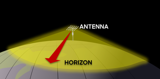
Line-of-sight propagation is a characteristic of electromagnetic radiation or acoustic wave propagation which means waves can only travel in a direct visual path from the source to the receiver without obstacles. Electromagnetic transmission includes light emissions traveling in a straight line. The rays or waves may be diffracted, refracted, reflected, or absorbed by the atmosphere and obstructions with material and generally cannot travel over the horizon or behind obstacles.
Radio propagation is the behavior of radio waves as they travel, or are propagated, from one point to another in vacuum, or into various parts of the atmosphere. As a form of electromagnetic radiation, like light waves, radio waves are affected by the phenomena of reflection, refraction, diffraction, absorption, polarization, and scattering. Understanding the effects of varying conditions on radio propagation has many practical applications, from choosing frequencies for amateur radio communications, international shortwave broadcasters, to designing reliable mobile telephone systems, to radio navigation, to operation of radar systems.

Effective radiated power (ERP), synonymous with equivalent radiated power, is an IEEE standardized definition of directional radio frequency (RF) power, such as that emitted by a radio transmitter. It is the total power in watts that would have to be radiated by a half-wave dipole antenna to give the same radiation intensity as the actual source antenna at a distant receiver located in the direction of the antenna's strongest beam. ERP measures the combination of the power emitted by the transmitter and the ability of the antenna to direct that power in a given direction. It is equal to the input power to the antenna multiplied by the gain of the antenna. It is used in electronics and telecommunications, particularly in broadcasting to quantify the apparent power of a broadcasting station experienced by listeners in its reception area.
In telecommunications, particularly in radio frequency engineering, signal strength refers to the transmitter power output as received by a reference antenna at a distance from the transmitting antenna. High-powered transmissions, such as those used in broadcasting, are expressed in dB-millivolts per metre (dBmV/m). For very low-power systems, such as mobile phones, signal strength is usually expressed in dB-microvolts per metre (dBμV/m) or in decibels above a reference level of one milliwatt (dBm). In broadcasting terminology, 1 mV/m is 1000 μV/m or 60 dBμ.
A link budget is an accounting of all of the power gains and losses that a communication signal experiences in a telecommunication system; from a transmitter, through a communication medium such as radio waves, cable, waveguide, or optical fiber, to the receiver. It is an equation giving the received power from the transmitter power, after the attenuation of the transmitted signal due to propagation, as well as the antenna gains and feedline and other losses, and amplification of the signal in the receiver or any repeaters it passes through. A link budget is a design aid, calculated during the design of a communication system to determine the received power, to ensure that the information is received intelligibly with an adequate signal-to-noise ratio. Randomly varying channel gains such as fading are taken into account by adding some margin depending on the anticipated severity of its effects. The amount of margin required can be reduced by the use of mitigating techniques such as antenna diversity or multiple-input and multiple-output (MIMO).
Non-line-of-sight (NLOS) radio propagation occurs outside of the typical line-of-sight (LOS) between the transmitter and receiver, such as in ground reflections. Near-line-of-sight conditions refer to partial obstruction by a physical object present in the innermost Fresnel zone.
The Egli model is a terrain model for radio frequency propagation. This model, which was first introduced by John Egli in his 1957 paper, was derived from real-world data on UHF and VHF television transmissions in several large cities. It predicts the total path loss for a point-to-point link. Typically used for outdoor line-of-sight transmission, this model provides the path loss as a single quantity.
The ITU terrain loss model is a radio propagation model that provides a method to predict the median path loss for a telecommunication link. Developed on the basis of diffraction theory, this model predicts the path loss as a function of the height of path blockage and the First Fresnel zone for the transmission link.
The COST Hata model is a radio propagation model that extends the urban Hata model to cover a more elaborated range of frequencies. It is the most often cited of the COST 231 models, also called the Hata Model PCS Extension. This model is the combination of empirical and deterministic models for estimating path loss in an urban area over frequency range of 800 MHz to 2000 MHz.
Young model is a radio propagation model that was built on the data collected on New York City. It typically models the behaviour of cellular communication systems in large cities.
The Lee model for area-to-area mode is a radio propagation model that operates around 900 MHz. Built as two different modes, this model includes an adjustment factor that can be adjusted to make the model more flexible to different regions of propagation.
The ITU single vegetative obstruction model is a radio propagation model that quantitatively estimates attenuation due to a single plant or tree standing in the middle of a telecommunication link.
The Lee model for point-to-point mode is a radio propagation model that operates around 900 MHz. Built as two different modes, this model includes an adjustment factor that can be adjusted to make the model more flexible to different regions of propagation.
The log-distance path loss model is a radio propagation model that predicts the path loss a signal encounters inside a building or densely populated areas over distance.
The Hata model is a radio propagation model for predicting the path loss of cellular transmissions in exterior environments, valid for microwave frequencies from 150 to 1500 MHz. It is an empirical formulation based on the data from the Okumura model, and is thus also commonly referred to as the Okumura–Hata model. The model incorporates the graphical information from Okumura model and develops it further to realize the effects of diffraction, reflection and scattering caused by city structures. Additionally, the Hata Model applies corrections for applications in suburban and rural environments.
This is an index to articles about terms used in discussion of radio propagation.

The two-rays ground-reflection model is a multipath radio propagation model which predicts the path losses between a transmitting antenna and a receiving antenna when they are in line of sight (LOS). Generally, the two antenna each have different height. The received signal having two components, the LOS component and the reflection component formed predominantly by a single ground reflected wave.

In the domain of wireless communication, air-to-ground channels (A2G) are used for linking airborne devices, such as drones and aircraft, with terrestrial communication equipment. These channels are instrumental in a wide array of applications, extending beyond commercial telecommunications — including important roles in 5G and forthcoming 6G networks, where aerial base stations are integral to Non-Terrestrial Networks — to encompass critical uses in emergency response, environmental monitoring, military communications, and the expanding domain of the internet of things (IoT). A comprehensive understanding of A2G channels, their operational mechanics, and distinct attributes is essential for the enhancement of wireless network performance.


