The decibel is a relative unit of measurement equal to one tenth of a bel (B). It expresses the ratio of two values of a power or root-power quantity on a logarithmic scale. Two signals whose levels differ by one decibel have a power ratio of 101/10 or root-power ratio of 101/20.

In telecommunications, orthogonal frequency-division multiplexing (OFDM) is a type of digital transmission used in digital modulation for encoding digital (binary) data on multiple carrier frequencies. OFDM has developed into a popular scheme for wideband digital communication, used in applications such as digital television and audio broadcasting, DSL internet access, wireless networks, power line networks, and 4G/5G mobile communications.
In telecommunication, the free-space path loss (FSPL) is the attenuation of radio energy between the feedpoints of two antennas that results from the combination of the receiving antenna's capture area plus the obstacle-free, line-of-sight (LoS) path through free space. The "Standard Definitions of Terms for Antennas", IEEE Std 145-1993, defines free-space loss as "The loss between two isotropic radiators in free space, expressed as a power ratio." It does not include any power loss in the antennas themselves due to imperfections such as resistance. Free-space loss increases with the square of distance between the antennas because the radio waves spread out by the inverse square law and decreases with the square of the wavelength of the radio waves. The FSPL is rarely used standalone, but rather as a part of the Friis transmission formula, which includes the gain of antennas. It is a factor that must be included in the power link budget of a radio communication system, to ensure that sufficient radio power reaches the receiver such that the transmitted signal is received intelligibly.
Noise figure (NF) and noise factor (F) are figures of merit that indicate degradation of the signal-to-noise ratio (SNR) that is caused by components in a signal chain. These figures of merit are used to evaluate the performance of an amplifier or a radio receiver, with lower values indicating better performance.
Path loss, or path attenuation, is the reduction in power density (attenuation) of an electromagnetic wave as it propagates through space. Path loss is a major component in the analysis and design of the link budget of a telecommunication system.
The propagation constant of a sinusoidal electromagnetic wave is a measure of the change undergone by the amplitude and phase of the wave as it propagates in a given direction. The quantity being measured can be the voltage, the current in a circuit, or a field vector such as electric field strength or flux density. The propagation constant itself measures the dimensionless change in magnitude or phase per unit length. In the context of two-port networks and their cascades, propagation constant measures the change undergone by the source quantity as it propagates from one port to the next.
Rayleigh fading is a statistical model for the effect of a propagation environment on a radio signal, such as that used by wireless devices.
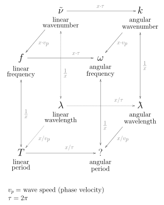
In the physical sciences, the wavenumber, also known as repetency, is the spatial frequency of a wave, measured in cycles per unit distance or radians per unit distance. It is analogous to temporal frequency, which is defined as the number of wave cycles per unit time or radians per unit time.

A parabolic antenna is an antenna that uses a parabolic reflector, a curved surface with the cross-sectional shape of a parabola, to direct the radio waves. The most common form is shaped like a dish and is popularly called a dish antenna or parabolic dish. The main advantage of a parabolic antenna is that it has high directivity. It functions similarly to a searchlight or flashlight reflector to direct radio waves in a narrow beam, or receive radio waves from one particular direction only. Parabolic antennas have some of the highest gains, meaning that they can produce the narrowest beamwidths, of any antenna type. In order to achieve narrow beamwidths, the parabolic reflector must be much larger than the wavelength of the radio waves used, so parabolic antennas are used in the high frequency part of the radio spectrum, at UHF and microwave (SHF) frequencies, at which the wavelengths are small enough that conveniently sized reflectors can be used.
In physics and engineering, the quality factor or Q factor is a dimensionless parameter that describes how underdamped an oscillator or resonator is. It is defined as the ratio of the initial energy stored in the resonator to the energy lost in one radian of the cycle of oscillation. Q factor is alternatively defined as the ratio of a resonator's centre frequency to its bandwidth when subject to an oscillating driving force. These two definitions give numerically similar, but not identical, results. Higher Q indicates a lower rate of energy loss and the oscillations die out more slowly. A pendulum suspended from a high-quality bearing, oscillating in air, has a high Q, while a pendulum immersed in oil has a low one. Resonators with high quality factors have low damping, so that they ring or vibrate longer.
Rain fade refers primarily to the absorption of a microwave radio frequency (RF) signal by atmospheric rain, snow, or ice, and losses which are especially prevalent at frequencies above 11 GHz. It also refers to the degradation of a signal caused by the electromagnetic interference of the leading edge of a storm front. Rain fade can be caused by precipitation at the uplink or downlink location. It does not need to be raining at a location for it to be affected by rain fade, as the signal may pass through precipitation many miles away, especially if the satellite dish has a low look angle. From 5% to 20% of rain fade or satellite signal attenuation may also be caused by rain, snow, or ice on the uplink or downlink antenna reflector, radome, or feed horn. Rain fade is not limited to satellite uplinks or downlinks, as it can also affect terrestrial point-to-point microwave links.

Continuous-wave radar is a type of radar system where a known stable frequency continuous wave radio energy is transmitted and then received from any reflecting objects. Individual objects can be detected using the Doppler effect, which causes the received signal to have a different frequency from the transmitted signal, allowing it to be detected by filtering out the transmitted frequency.
Non-line-of-sight (NLOS) radio propagation occurs outside of the typical line-of-sight (LOS) between the transmitter and receiver, such as in ground reflections. Near-line-of-sight conditions refer to partial obstruction by a physical object present in the innermost Fresnel zone.
Weissberger’s modified exponential decay model, or simply, Weissberger’s model, is a radio wave propagation model that estimates the path loss due to the presence of one or more trees in a point-to-point telecommunication link. This model belongs to the category Foliage or Vegetation models.
The ITU terrain loss model is a radio propagation model that provides a method to predict the median path loss for a telecommunication link. Developed on the basis of diffraction theory, this model predicts the path loss as a function of the height of path blockage and the First Fresnel zone for the transmission link.
The ITU terrestrial model for one terminal in woodland is a radio propagation model belonging to the class of foliage models. This model is a successor of the early ITU model.
The ITU indoor propagation model, also known as ITU model for indoor attenuation, is a radio propagation model that estimates the path loss inside a room or a closed area inside a building delimited by walls of any form. Suitable for appliances designed for indoor use, this model approximates the total path loss an indoor link may experience.
Radar engineering is the design of technical aspects pertaining to the components of a radar and their ability to detect the return energy from moving scatterers — determining an object's position or obstruction in the environment. This includes field of view in terms of solid angle and maximum unambiguous range and velocity, as well as angular, range and velocity resolution. Radar sensors are classified by application, architecture, radar mode, platform, and propagation window.
Carrier frequency offset (CFO) is one of many non-ideal conditions that may affect in baseband receiver design. In designing a baseband receiver, we should notice not only the degradation invoked by non-ideal channel and noise, we should also regard RF and analog parts as the main consideration. Those non-idealities include sampling clock offset, IQ imbalance, power amplifier, phase noise and carrier frequency offset nonlinearity.

In the domain of wireless communication, air-to-ground channels (A2G) are used for linking airborne devices, such as drones and aircraft, with terrestrial communication equipment. These channels are instrumental in a wide array of applications, extending beyond commercial telecommunications — including important roles in 5G and forthcoming 6G networks, where aerial base stations are integral to Non-Terrestrial Networks — to encompass critical uses in emergency response, environmental monitoring, military communications, and the expanding domain of the internet of things (IoT). A comprehensive understanding of A2G channels, their operational mechanics, and distinct attributes is essential for the enhancement of wireless network performance.


