Related Research Articles

A bogie is a chassis or framework that carries a wheelset, attached to a vehicle—a modular subassembly of wheels and axles. Bogies take various forms in various modes of transport. A bogie may remain normally attached or be quickly detachable. It may include a suspension component within it, or be solid and in turn be suspended ; it may be mounted on a swivel, as traditionally on a railway carriage or locomotive, additionally jointed and sprung, or held in place by other means.
On a steam locomotive, a driving wheel is a powered wheel which is driven by the locomotive's pistons. On a conventional, non-articulated locomotive, the driving wheels are all coupled together with side rods ; normally one pair is directly driven by the main rod which is connected to the end of the piston rod; power is transmitted to the others through the side rods.
Orenstein & Koppel was a major German engineering company specialising in railway vehicles, escalators, and heavy equipment. It was founded on April 1, 1876, in Berlin by Benno Orenstein and Arthur Koppel.

The GWR 4100 Class was a class of steam locomotives in the Great Western Railway (GWR) of the United Kingdom.
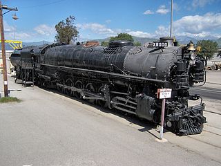
The Union Pacific Railroad 9000 Class was a class of 88 steam locomotives, built by ALCO for the Union Pacific between 1926 and 1930.
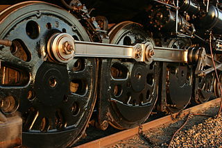
A coupling rod or side rod connects the driving wheels of a locomotive. Steam locomotives in particular usually have them, but some diesel and electric locomotives, especially older ones and shunter locomotives, also have them. The coupling rods transfer the power of drive to all wheels.
B-B and Bo-Bo are the Association of American Railroads (AAR) and British classifications of wheel arrangement for railway locomotives with four axles in two individual bogies. They are equivalent to the B′B′ and Bo′Bo′ classifications in the UIC system. The arrangement of two, two-axled, bogies is a common wheel arrangement for modern electric and diesel locomotives.

A jackshaft is an intermediate shaft used to transfer power from a powered shaft such as the output shaft of an engine or motor to driven shafts such as the drive axles of a locomotive. As applied to railroad locomotives in the 19th and 20th centuries, jackshafts were typically in line with the drive axles of locomotives and connected to them by side rods. In general, each drive axle on a locomotive is free to move about one inch (2.5 cm) vertically relative to the frame, with the locomotive weight carried on springs. This means that if the engine, motor or transmission is rigidly attached to the locomotive frame, it cannot be rigidly connected to the axle. This problem can be solved by mounting the jackshaft on unsprung bearings and using side-rods or chain drives.

A Krauss-Helmholtz bogie (Krauss-Helmholtz-Lenkgestell) is a mechanism used on steam locomotives and some electric locomotives to improve curve running.
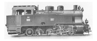
A Luttermöller axle is an unusual steam locomotive component. Steam locomotives with several axles or wheelsets connected to one another by coupling rods are not able to negotiate tight curves well. In order to assist such locomotives, the manager of the Orenstein & Koppel factory in Berlin, Dr. Luttermöller, built the axle system named after him.

The Beugniot lever (Beugniot-Hebel) is a mechanical device used on a number of locomotives to improve curve running. It was named after its inventor Édouard Beugniot.

The Klien-Lindner axle is a special type of hollow driving axle on steam locomotives that enable better curve running due to its ability to slide transversely. It was developed by the German engineers, Ewald Klien and Heinrich Lindner, of the Royal Saxon State Railways.
The PRR J1 was a class of 2-10-4 "Texas" type steam locomotives built between 1942 and 1944. The J1 had over 95,000 pounds-force (422.6 kN) of tractive effort, plus an additional 15,000 lbf (66.7 kN) if the booster engine was used.

The Gölsdorf axle system is used on railway Gölsdorf locomotives to achieve quiet running and low wear-and-tear when negotiating curves. The axle system comprises a combination of fixed axles and axles that can slide transversely, all within a single, rigid locomotive frame. The system was invented by a young Austrian locomotive builder, Karl Gölsdorf, around the end of the 19th century. The first locomotive to use this principle entered service in 1897.

The South African Railways Class 18 2-10-2 of 1927 was a steam locomotive.

The Central South African Railways Rack 4-6-4RT of 1905 was a South African steam locomotive from the pre-Union era in Transvaal Colony.

The Ferrovie dello Stato Class 640 is a class of 2-6-0 'Mogul' steam locomotives in Italy. Commonly nicknamed "Signorine", a nickname shared with the similar Class 625, these locomotives were the first superheated steam locomotives in Italy.
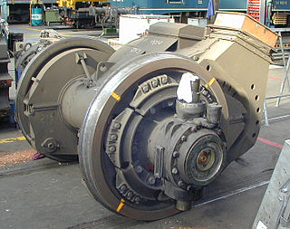
A cannon bearing or cannon box bearing is an arrangement of bearings on a shaft, usually an axle, where two bearings are mounted in an enclosed tube.
A monomotor bogie is a form of traction bogie used for an electric locomotive or diesel-electric locomotive. It is distinguished by having a single traction motor on each bogie.

Rigid-framed electric locomotives were some of the first generations of electric locomotive design. When these began the traction motors of these early locomotives, particularly with AC motors, were too large and heavy to be mounted directly to the axles and so were carried on the frame. One of the initial simplest wheel arrangements for a mainline electric locomotive, from around 1900, was the 1′C1′ arrangement, in UIC classification.
References
- ↑ For example, the Pennsylvania class I-1s 2-10-0 had no flange on the middle drivers.
- ↑ Hollingsworth, B. and Cook, A. Steam Locomotives. 2000, Salamander Books. ISBN 0-86288-346-6. 72-73
- ↑ Hollingsworth & Cook. 133. "Zara" is Giuseppe Zara, the Chief Mechanical Engineer of the Italian State Railways when the class 640 was designed.
- ↑ Swengel, F.M. The American Steam Locomotive. 1967, Midwest Rail Publications, Inc. 222
- ↑ Hollingsworth & Cook. 140
- ↑ Hollingsworth & Cook. 104