A sextant is a doubly reflecting navigation instrument that measures the angular distance between two visible objects. The primary use of a sextant is to measure the angle between an astronomical object and the horizon for the purposes of celestial navigation.

A galvanometer is an electromechanical measuring instrument for electric current. Early galvanometers were uncalibrated, but improved versions, called ammeters, were calibrated and could measure the flow of current more precisely. Galvanometers work by deflecting a pointer in response to an electric current flowing through a coil in a constant magnetic field. The mechanism is also used as an actuator in applications such as hard disks.

A sundial is a horological device that tells the time of day when direct sunlight shines by the apparent position of the Sun in the sky. In the narrowest sense of the word, it consists of a flat plate and a gnomon, which casts a shadow onto the dial. As the Sun appears to move through the sky, the shadow aligns with different hour-lines, which are marked on the dial to indicate the time of day. The style is the time-telling edge of the gnomon, though a single point or nodus may be used. The gnomon casts a broad shadow; the shadow of the style shows the time. The gnomon may be a rod, wire, or elaborately decorated metal casting. The style must be parallel to the axis of the Earth's rotation for the sundial to be accurate throughout the year. The style's angle from horizontal is equal to the sundial's geographical latitude.

Flight instruments are the instruments in the cockpit of an aircraft that provide the pilot with data about the flight situation of that aircraft, such as altitude, airspeed, vertical speed, heading and much more other crucial information in flight. They improve safety by allowing the pilot to fly the aircraft in level flight, and make turns, without a reference outside the aircraft such as the horizon. Visual flight rules (VFR) require an airspeed indicator, an altimeter, and a compass or other suitable magnetic direction indicator. Instrument flight rules (IFR) additionally require a gyroscopic pitch-bank, direction and rate of turn indicator, plus a slip-skid indicator, adjustable altimeter, and a clock. Flight into instrument meteorological conditions (IMC) require radio navigation instruments for precise takeoffs and landings.

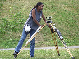
A theodolite is a precision optical instrument for measuring angles between designated visible points in the horizontal and vertical planes. The traditional use has been for land surveying, but it is also used extensively for building and infrastructure construction, and some specialized applications such as meteorology and rocket launching.

An optical telescope gathers and focuses light mainly from the visible part of the electromagnetic spectrum, to create a magnified image for direct visual inspection, to make a photograph, or to collect data through electronic image sensors.

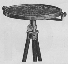
An alidade or a turning board is a device that allows one to sight a distant object and use the line of sight to perform a task. This task can be, for example, to triangulate a scale map on site using a plane table drawing of intersecting lines in the direction of the object from two or more points or to measure the angle and horizontal distance to the object from some reference point's polar measurement. Angles measured can be horizontal, vertical or in any chosen plane.
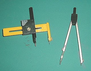
A compass, also commonly known as a pair of compasses, is a technical drawing instrument that can be used for inscribing circles or arcs. As dividers, it can also be used as a tool to mark out distances, in particular, on maps. Compasses can be used for mathematics, drafting, navigation and other purposes.

A reticle, or reticule also known as a graticule, is a pattern of fine lines or markings built into the eyepiece of an optical device such as a telescopic sight, spotting scope, theodolite, optical microscope or the screen of an oscilloscope, to provide measurement references during visual inspections. Today, engraved lines or embedded fibers may be replaced by a digital image superimposed on a screen or eyepiece. Both terms may be used to describe any set of patterns used for aiding visual measurements and calibrations, but in modern use reticle is most commonly used for weapon sights, while graticule is more widely used for non-weapon measuring instruments such as oscilloscope display, astronomic telescopes, microscopes and slides, surveying instruments and other similar devices.
Levelling or leveling is a branch of surveying, the object of which is to establish or verify or measure the height of specified points relative to a datum. It is widely used in geodesy and cartography to measure vertical position with respect to a vertical datum, and in construction to measure height differences of construction artifacts.
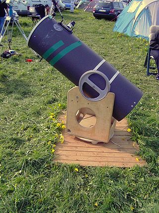
An altazimuth mount or alt-azimuth mount is a simple two-axis mount for supporting and rotating an instrument about two perpendicular axes – one vertical and the other horizontal. Rotation about the vertical axis varies the azimuth of the pointing direction of the instrument. Rotation about the horizontal axis varies the altitude angle of the pointing direction.

The octant, also called a reflecting quadrant, is a reflecting instrument used in navigation.

A level is an optical instrument used to establish or verify points in the same horizontal plane in a process known as levelling. It is used in conjunction with a levelling staff to establish the relative height or levels of objects or marks. It is widely used in surveying and construction to measure height differences and to transfer, measure, and set heights of known objects or marks.
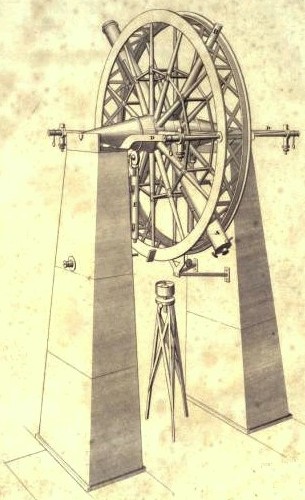
The meridian circle is an instrument for timing of the passage of stars across the local meridian, an event known as a culmination, while at the same time measuring their angular distance from the nadir. These are special purpose telescopes mounted so as to allow pointing only in the meridian, the great circle through the north point of the horizon, the north celestial pole, the zenith, the south point of the horizon, the south celestial pole, and the nadir. Meridian telescopes rely on the rotation of the sky to bring objects into their field of view and are mounted on a fixed, horizontal, east–west axis.
Polar alignment is the act of aligning the rotational axis of a telescope's equatorial mount or a sundial's gnomon with a celestial pole to parallel Earth's axis.
Reflecting instruments are those that use mirrors to enhance their ability to make measurements. In particular, the use of mirrors permits one to observe two objects simultaneously while measuring the angular distance between the objects. While reflecting instruments are used in many professions, they are primarily associated with celestial navigation as the need to solve navigation problems, in particular the problem of the longitude, was the primary motivation in their development.

The Course Setting Bomb Sight (CSBS) is the canonical vector bombsight, the first practical system for properly accounting for the effects of wind when dropping bombs. It is also widely referred to as the Wimperis sight after its inventor, Harry Wimperis.
Temporary adjustments are a set of operations which are performed on a theodolite to make it ready for taking observations. These include its initial setting up on a tripod or other stand, centering, levelling up and focusing of eyepiece.

The Post Plotting Instrument, or simply Post Instrument and sometimes the Observer Instrument, was the standard optical sighting system used by the UK's Royal Observer Corps (ROC) to determine the location of aircraft. It was used during the period from the mid-1930s into the early 1950s, and was one of the main sources of daytime tracking information during World War II.

Burt's solar compass or astronomical compass/sun compass is a surveying instrument that makes use of the Sun's direction instead of magnetism. William Austin Burt invented his solar compass in 1835. The solar compass works on the principle that the direction to the Sun at a specified time can be calculated if the position of the observer on the surface of the Earth is known, to a similar precision. The direction can be described in terms of the angle of the Sun relative to the axis of rotation of the planet.