A crankshaft is a mechanical component used in a piston engine to convert the reciprocating motion into rotational motion. The crankshaft is a rotating shaft containing one or more crankpins, that are driven by the pistons via the connecting rods.

A reciprocating engine, also often known as a piston engine, is typically a heat engine that uses one or more reciprocating pistons to convert high temperature and high pressure into a rotating motion. This article describes the common features of all types. The main types are: the internal combustion engine, used extensively in motor vehicles; the steam engine, the mainstay of the Industrial Revolution; and the Stirling engine for niche applications. Internal combustion engines are further classified in two ways: either a spark-ignition (SI) engine, where the spark plug initiates the combustion; or a compression-ignition (CI) engine, where the air within the cylinder is compressed, thus heating it, so that the heated air ignites fuel that is injected then or earlier.

A steam engine is a heat engine that performs mechanical work using steam as its working fluid. The steam engine uses the force produced by steam pressure to push a piston back and forth inside a cylinder. This pushing force can be transformed, by a connecting rod and crank, into rotational force for work. The term "steam engine" is most commonly applied to reciprocating engines as just described, although some authorities have also referred to the steam turbine and devices such as Hero's aeolipile as "steam engines". The essential feature of steam engines is that they are external combustion engines, where the working fluid is separated from the combustion products. The ideal thermodynamic cycle used to analyze this process is called the Rankine cycle. In general usage, the term steam engine can refer to either complete steam plants, such as railway steam locomotives and portable engines, or may refer to the piston or turbine machinery alone, as in the beam engine and stationary steam engine.

In mechanical engineering, a crosshead is a mechanical joint used as part of the slider-crank linkages of long reciprocating engines and reciprocating compressors to eliminate sideways force on the piston. Also, the crosshead enables the connecting rod to freely move outside the cylinder. Because of the very small bore-to-stroke ratio on such engines, the connecting rod would hit the cylinder walls and block the engine from rotating if the piston was attached directly to the connecting rod like on trunk engines. Therefore, the longitudinal dimension of the crosshead must be matched to the stroke of the engine.

A flat-twin engine is a two-cylinder internal combustion engine with the cylinders on opposite sides of the crankshaft. The most common type of flat-twin engine is the boxer-twin engine, where both pistons move inwards and outwards at the same time.

A crank is an arm attached at a right angle to a rotating shaft by which circular motion is imparted to or received from the shaft. When combined with a connecting rod, it can be used to convert circular motion into reciprocating motion, or vice versa. The arm may be a bent portion of the shaft, or a separate arm or disk attached to it. Attached to the end of the crank by a pivot is a rod, usually called a connecting rod (conrod).

A connecting rod, also called a 'con rod', is the part of a piston engine which connects the piston to the crankshaft. Together with the crank, the connecting rod converts the reciprocating motion of the piston into the rotation of the crankshaft. The connecting rod is required to transmit the compressive and tensile forces from the piston. In its most common form, in an internal combustion engine, it allows pivoting on the piston end and rotation on the shaft end.
Torsional vibration is the angular vibration of an object - commonly a shaft - along its axis of rotation. Torsional vibration is often a concern in power transmission systems using rotating shafts or couplings, where it can cause failures if not controlled. A second effect of torsional vibrations applies to passenger cars. Torsional vibrations can lead to seat vibrations or noise at certain speeds. Both reduce the comfort.
Engine balance refers to how the inertial forces produced by moving parts in an internal combustion engine or steam engine are neutralised with counterweights and balance shafts, to prevent unpleasant and potentially damaging vibration. The strongest inertial forces occur at crankshaft speed and balance is mandatory, while forces at twice crankshaft speed can become significant in some cases.

Reciprocating motion, also called reciprocation, is a repetitive up-and-down or back-and-forth linear motion. It is found in a wide range of mechanisms, including reciprocating engines and pumps. The two opposite motions that comprise a single reciprocation cycle are called strokes.
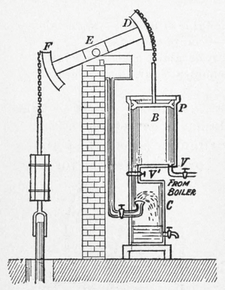
A beam engine is a type of steam engine where a pivoted overhead beam is used to apply the force from a vertical piston to a vertical connecting rod. This configuration, with the engine directly driving a pump, was first used by Thomas Newcomen around 1705 to remove water from mines in Cornwall. The efficiency of the engines was improved by engineers including James Watt, who added a separate condenser; Jonathan Hornblower and Arthur Woolf, who compounded the cylinders; and William McNaught, who devised a method of compounding an existing engine. Beam engines were first used to pump water out of mines or into canals but could be used to pump water to supplement the flow for a waterwheel powering a mill.

A crankpin or crank pin, also known as a rod bearing journal, is a mechanical device in an engine which connects the crankshaft to the connecting rod for each cylinder. It has a cylindrical surface, to allow the crankpin to rotate relative to the "big end" of the connecting rod.

An axial engine is a type of reciprocating engine with pistons arranged around an output shaft with their axes parallel to the shaft. Barrel refers to the cylindrical shape of the cylinder group whilst the Z-crank alludes to the shape of the crankshaft.
In rail terminology, hammer blow or dynamic augment is a vertical force which alternately adds to and subtracts from the locomotive's weight on a wheel. It is transferred to the track by the driving wheels of many steam locomotives. It is an out-of-balance force on the wheel. It is the result of a compromise when a locomotive's wheels are unbalanced to off-set horizontal reciprocating masses, such as connecting rods and pistons, to improve the ride. The hammer blow may cause damage to the locomotive and track if the wheel/rail force is high enough.

In a reciprocating engine, the dead centre is the position of a piston in which it is either farthest from, or nearest to, the crankshaft. The former is known as top dead centre (TDC) while the latter is known as bottom dead centre (BDC).

Musgrave's non-dead-centre engine was a stationary steam engine of unusual design, intended to solve the problem of stopping on dead centre. It was designed in 1887 to serve as a marine engine. It used a pair of linked cylinders to prevent the engine from stopping in a position where no turning force can be applied. At least one engine is known to survive.
In mechanical engineering, the cylinders of reciprocating engines are often classified by whether they are single- or double-acting, depending on how the working fluid acts on the piston.

A return connecting rod, return piston rod or double piston rod engine or back-acting engine is a particular layout for a steam engine.

The Lap Engine is a beam engine designed by James Watt, built by Boulton and Watt in 1788. It is now preserved at the Science Museum, London.
A slider-crank linkage is a four-link mechanism with three revolute joints and one prisimatic (sliding) joint. The rotation of the crank drives the linear movement of the slider, or the expansion of gases against a sliding piston in a cylinder can drive the rotation of the crank.

