Distributed amplifier

Last updated

Distributed amplifiers are circuit designs that incorporate transmission line theory into traditional amplifier design to obtain a larger gain-bandwidth product than is realizable by conventional circuits.

The process of circuit design can cover systems ranging from complex electronic systems all the way down to the individual transistors within an integrated circuit. For simple circuits the design process can often be done by one person without needing a planned or structured design process, but for more complex designs, teams of designers following a systematic approach with intelligently guided computer simulation are becoming increasingly common. In integrated circuit design automation, the term "circuit design" often refers to the step of the design cycle which outputs the schematics of the integrated circuit. Typically this is the step between logic design and physical design.

Transmission line specialized cable or other structure designed to carry alternating current of radio frequency

In radio-frequency engineering, a transmission line is a specialized cable or other structure designed to conduct alternating current of radio frequency, that is, currents with a frequency high enough that their wave nature must be taken into account. Transmission lines are used for purposes such as connecting radio transmitters and receivers with their antennas, distributing cable television signals, trunklines routing calls between telephone switching centres, computer network connections and high speed computer data buses.

Electronic circuit electrical circuit with active components such as transistors, valves and integrated circuits; electrical network that contains active electronic components, generally nonlinear and require complex design and analysis tools

An electronic circuit is composed of individual electronic components, such as resistors, transistors, capacitors, inductors and diodes, connected by conductive wires or traces through which electric current can flow. To be referred to as electronic, rather than electrical, generally at least one active component must be present. The combination of components and wires allows various simple and complex operations to be performed: signals can be amplified, computations can be performed, and data can be moved from one place to another.

Contents

N-stage traveling-wave amplifier N-stage traveling-wave amplifier.svg
N-stage traveling-wave amplifier

History

The design of the distributed amplifiers was first formulated by William S. Percival in 1936. [1] In that year Percival proposed a design by which the transconductances of individual vacuum tubes could be added linearly without lumping their element capacitances at the input and output, thus arriving at a circuit that achieved a gain-bandwidth product greater than that of an individual tube. Percival's design did not gain widespread awareness however, until a publication on the subject was authored by Ginzton, Hewlett, Jasberg, and Noe in 1948. [2] It is to this later paper that the term distributed amplifier can actually be traced. Traditionally, DA design architectures were realized using vacuum tube technology.

Transconductance, also infrequently called mutual conductance, is the electrical characteristic relating the current through the output of a device to the voltage across the input of a device. Conductance is the reciprocal of resistance.

Vacuum tube Device that controls electric current between electrodes in an evacuated container

In electronics, a vacuum tube, an electron tube, or valve or, colloquially, a tube, is a device that controls electric current flow in a high vacuum between electrodes to which an electric potential difference has been applied.

Dr Edward Leonard Ginzton was a Ukrainian-American engineer.

Current technology

More recently, III-V semiconductor technologies, such as GaAs [3] [4] [5] and InP have been used. [6] [7] These have superior performance resulting from higher bandgaps (higher electron mobility), higher saturated electron velocity, higher breakdown voltages and higher-resistivity substrates. The latter contributes much to the availability of higher quality-factor (Q-factor or simply Q) integrated passive devices in the III-V semiconductor technologies.

A semiconductor material has an electrical conductivity value falling between that of a conductor, such as metallic copper, and an insulator, such as glass. Its resistance decreases as its temperature increases, which is behaviour opposite to that of a metal. Its conducting properties may be altered in useful ways by the deliberate, controlled introduction of impurities ("doping") into the crystal structure. Where two differently-doped regions exist in the same crystal, a semiconductor junction is created. The behavior of charge carriers which include electrons, ions and electron holes at these junctions is the basis of diodes, transistors and all modern electronics. Some examples of semiconductors are silicon, germanium, gallium arsenide, and elements near the so-called "metalloid staircase" on the periodic table. After silicon, gallium arsenide is the second most common semiconductor and is used in laser diodes, solar cells, microwave-frequency integrated circuits and others. Silicon is a critical element for fabricating most electronic circuits.

Integrated passive devices

Integrated Passive Devices (IPD's) "or Integrated Passive Components (IPC's)" are attracting an increasing interest due to constant needs of handheld wireless devices to further decrease in size and cost and increase in functionality.

To meet the marketplace demands on cost, size, and power consumption of monolithic microwave integrated circuits (MMICs), research continues in the development of mainstream digital bulk-CMOS processes for such purposes. The continuous scaling of feature sizes in current IC technologies has enabled microwave and mm-wave CMOS circuits to directly benefit from the resulting increased unity-gain frequencies of the scaled technology. This device scaling, along with the advanced process control available in today's technologies, has recently made it possible to reach a transition frequency (ft) of 170 GHz and a maximum oscillation frequency (fmax) of 240 GHz in a 90 nm CMOS process. [8]

Microwave form of electromagnetic radiation

Microwaves are a form of electromagnetic radiation with wavelengths ranging from about one meter to one millimeter; with frequencies between 300 MHz (1 m) and 300 GHz (1 mm). Different sources define different frequency ranges as microwaves; the above broad definition includes both UHF and EHF bands. A more common definition in radio engineering is the range between 1 and 100 GHz. In all cases, microwaves include the entire SHF band at minimum. Frequencies in the microwave range are often referred to by their IEEE radar band designations: S, C, X, Ku, K, or Ka band, or by similar NATO or EU designations.

Digital data, in information theory and information systems, is the discrete, discontinuous representation of information or works. Numbers and letters are commonly used representations.

Oscillation repetitive variation of some measure about a central value

Oscillation is the repetitive variation, typically in time, of some measure about a central value or between two or more different states. The term vibration is precisely used to describe mechanical oscillation. Familiar examples of oscillation include a swinging pendulum and alternating current.

Theory of operation

The operation of the DA can perhaps be most easily understood when explained in terms of the traveling-wave tube amplifier (TWTA). The DA consists of a pair of transmission lines with characteristic impedances of Z0 independently connecting the inputs and outputs of several active devices. An RF signal is thus supplied to the section of transmission line connected to the input of the first device. As the input signal propagates down the input line, the individual devices respond to the forward traveling input step by inducing an amplified complementary forward traveling wave on the output line. This assumes the delays of the input and output lines are made equal through selection of propagation constants and lengths of the two lines and as such the output signals from each individual device sum in phase. Terminating resistors Zg and Zd are placed to minimize destructive reflections.

Traveling-wave tube

A traveling-wave tube or traveling-wave tube amplifier is a specialized vacuum tube that is used in electronics to amplify radio frequency (RF) signals in the microwave range. The TWT belongs to a category of "linear beam" tubes, such as the klystron, in which the radio wave is amplified by absorbing power from a beam of electrons as it passes down the tube. Although there are various types of TWT, two major categories are:

Characteristic impedance ratio of the amplitudes of voltage and current of a single wave propagating along the line

The characteristic impedance or surge impedance (usually written Z0) of a uniform transmission line is the ratio of the amplitudes of voltage and current of a single wave propagating along the line; that is, a wave travelling in one direction in the absence of reflections in the other direction. Alternatively and equivalently it can be defined as the input impedance of a transmission line when its length is infinite. Characteristic impedance is determined by the geometry and materials of the transmission line and, for a uniform line, is not dependent on its length. The SI unit of characteristic impedance is the ohm.

Wave propagation is any of the ways in which waves travel.

The transconductive gain of each device is gm and the output impedance seen by each transistor is half the characteristic impedance of the transmission line. So that the overall voltage gain of the DA is:

Gain (electronics) ability of a  circuit to increase the power or amplitude of a signal

In electronics, gain is a measure of the ability of a two-port circuit to increase the power or amplitude of a signal from the input to the output port by adding energy converted from some power supply to the signal. It is usually defined as the mean ratio of the signal amplitude or power at the output port to the amplitude or power at the input port. It is often expressed using the logarithmic decibel (dB) units. A gain greater than one, that is amplification, is the defining property of an active component or circuit, while a passive circuit will have a gain of less than one.

Electrical impedance intensive physical property

Electrical impedance is the measure of the opposition that a circuit presents to a current when a voltage is applied. The term complex impedance may be used interchangeably.

Transistor semiconductor device used to amplify and switch electronic signals and electrical power

A transistor is a semiconductor device used to amplify or switch electronic signals and electrical power. It is composed of semiconductor material usually with at least three terminals for connection to an external circuit. A voltage or current applied to one pair of the transistor's terminals controls the current through another pair of terminals. Because the controlled (output) power can be higher than the controlling (input) power, a transistor can amplify a signal. Today, some transistors are packaged individually, but many more are found embedded in integrated circuits.

Av = ½ n·gm·Z0, where n is the number of stages.

Neglecting losses, the gain demonstrates a linear dependence on the number of devices (stages). Unlike the multiplicative nature of a cascade of conventional amplifiers, the DA demonstrates an additive quality. It is this synergistic property of the DA architecture that makes it possible for it to provide gain at frequencies beyond that of the unity-gain frequency of the individual stages. In practice, the number of stages is limited by the diminishing input signal resulting from attenuation on the input line. Means of determining the optimal number of stages are discussed below. Bandwidth is typically limited by impedance mismatches brought about by frequency dependent device parasitics.

The DA architecture introduces delay in order to achieve its broadband gain characteristics. This delay is a desired feature in the design of another distributive system called the distributed oscillator.

Lumped elements

Delay lines are made of lumped elements of L and C. The parasitic L and the C from the transistors are used for this and usually some L is added to raise the line impedance. Because of the Miller effect in the common source amplifier the input and the output transmission line are coupled. For example, for voltage inverting and current amplifying the input and the output form a shielded balanced line. The current is increasing in the output transmission line with every subsequent transistor, and therefore less and less L is added to keep the voltage constant and more and more extra C is added to keep the velocity constant. This C can come from parasitics of a second stage. These delay lines do not have a flat dispersion near their cut off, so it is important to use the same L-C periodicity in the input and the output. If inserting transmission lines, input and output will disperse away from each other.

For a distributed amplifier the input is fed in series into the amplifiers and parallel out of them. To avoid losses in the input, no input signal is allowed to leak through. This is avoided by using a balanced input and output also known as push–pull amplifier. Then all signals which leak through the parasitic capacitances cancel. The output is combined in a delay line with decreasing impedance. For narrow band operation other methods of phase-matching are possible, which avoid feeding the signal through multiple coils and capacitors. This may be useful for power-amplifiers.

The single amplifiers can be of any class. There may be some synergy between distributed class E/F amplifiers and some phase-matching methods. Only the fundamental frequency is used in the end, so this is the only frequency, which travels through the delay line version.

Because of the Miller effect a common source transistor acts as a capacitor (non inverting) at high frequencies and has an inverting transconductance at low frequencies. The channel of the transistor has three dimensions. One dimension, the width, is chosen depending on the current needed. The trouble is for a single transistor parasitic capacitance and gain both scale linearly with the width. For the distributed amplifier the capacitance – that is the width – of the single transistor is chosen based on the highest frequency and the width needed for the current is split across all transistors.

Applications

Note that those termination resistors are usually not used in CMOS, but the losses due to these are small in typical applications. In solid state power amplifiers often multiple discrete transistors are used for power reasons anyway. If all transistors are driven in a synchronized fashion a very high gate drive power is needed. For frequencies at which small and efficient coils are available distributed amplifiers are more efficient.

Voltage can be amplified by a common gate transistor, which shows no miller effect and no unit gain frequency cut off. Adding this yields the cascode configuration. The common gate configuration is incompatible with CMOS; it adds a resistor, that means loss, and is more suited for broadband than for high efficiency applications.

See also

Related Research Articles

Amplifier electronic device that can increase the power of a signal

An amplifier, electronic amplifier or (informally) amp is an electronic device that can increase the power of a signal. It is a two-port electronic circuit that uses electric power from a power supply to increase the amplitude of a signal applied to its input terminals, producing a proportionally greater amplitude signal at its output. The amount of amplification provided by an amplifier is measured by its gain: the ratio of output voltage, current, or power to input. An amplifier is a circuit that has a power gain greater than one.

Circulator passive non-reciprocal three- or four-port device, in which a microwave or radio frequency signal entering any port is transmitted to the next port in rotation (only)

A circulator is a passive, non-reciprocal three- or four-port device, in which a microwave or radio-frequency signal entering any port is transmitted to the next port in rotation (only). A port in this context is a point where an external waveguide or transmission line, connects to the device. For a three-port circulator, a signal applied to port 1 only comes out of port 2; a signal applied to port 2 only comes out of port 3; a signal applied to port 3 only comes out of port 1, so to up to a phase-factor, the scattering matrix for an ideal three-port circulator is

CMOS technology for constructing integrated circuits

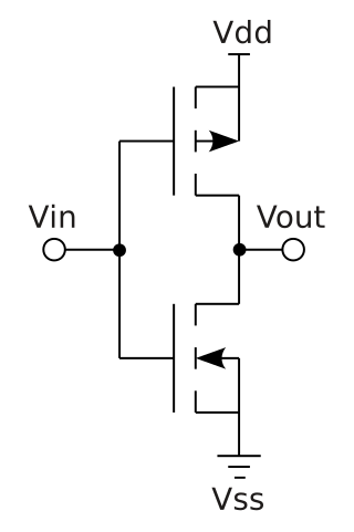
Complementary metal–oxide–semiconductor (CMOS) is a technology for constructing integrated circuits, employing MOSFET transistors. CMOS technology is used in microprocessors, microcontrollers, static RAM, and other digital logic circuits. CMOS technology is also used for several analog circuits such as image sensors, data converters, and highly integrated transceivers for many types of communication. Frank Wanlass invented CMOS in 1963 while at Fairchild Semiconductor and was granted US patent 3,356,858 in 1967. In this groundbreaking patent, the fabrication of CMOS devices was outlined, on the basis of thermal oxidation of a silicon substrate to yield a layer of silicon dioxide located between the drain contact and the source contact.

A low-noise amplifier (LNA) is an electronic amplifier that amplifies a very low-power signal without significantly degrading its signal-to-noise ratio. A typical amplifier increases the power of both the signal and the noise present at its input, whereas LNAs are designed to amplify a signal while minimizing additional noise. Designers can minimize additional noise by using low-noise components, operating points, and circuit topologies. Minimizing additional noise must balance with other goals such as power gain and impedance matching.

Common base

In electronics, a common-base amplifier is one of three basic single-stage bipolar junction transistor (BJT) amplifier topologies, typically used as a current buffer or voltage amplifier.

Preamplifier Circuit that prepares a signal for amplification

A preamplifier is an electronic amplifier that converts a weak electrical signal into an output signal strong enough to be noise-tolerant and strong enough for further processing, or for sending to a power amplifier and a loudspeaker. Without this, the final signal would be noisy or distorted. They are typically used to amplify signals from analog sensors such as microphones and pickups. Because of this, the preamplifier is often placed close to the sensor to reduce the effects of noise and interference.

The Hartley oscillator is an electronic oscillator circuit in which the oscillation frequency is determined by a tuned circuit consisting of capacitors and inductors, that is, an LC oscillator. The circuit was invented in 1915 by American engineer Ralph Hartley. The distinguishing feature of the Hartley oscillator is that the tuned circuit consists of a single capacitor in parallel with two inductors in series, and the feedback signal needed for oscillation is taken from the center connection of the two inductors.

Buffer amplifier electronic amplifier, a circuit component

A buffer amplifier is one that provides electrical impedance transformation from one circuit to another, with the aim of preventing the signal source from being affected by whatever currents that the load may produce. The signal is 'buffered from' load currents. Two main types of buffer exist: the voltage buffer and the current buffer.

Common emitter

In electronics, a common-emitter amplifier is one of three basic single-stage bipolar-junction-transistor (BJT) amplifier topologies, typically used as the voltage amplifier.

Input impedance

The input impedance of an electrical network is the measure of the opposition to current (impedance), both static (resistance) and dynamic (reactance), into the load network that is external to the electrical source. The input admittance (1/impedance) is a measure of the load's propensity to draw current. The source network is the portion of the network that transmits power, and the load network is the portion of the network that consumes power.

A Colpitts oscillator, invented in 1918 by American engineer Edwin H. Colpitts, is one of a number of designs for LC oscillators, electronic oscillators that use a combination of inductors (L) and capacitors (C) to produce an oscillation at a certain frequency. The distinguishing feature of the Colpitts oscillator is that the feedback for the active device is taken from a voltage divider made of two capacitors in series across the inductor.

Common gate

In electronics, a common-gate amplifier is one of three basic single-stage field-effect transistor (FET) amplifier topologies, typically used as a current buffer or voltage amplifier. In this circuit the source terminal of the transistor serves as the input, the drain is the output and the gate is connected to ground, or "common," hence its name. The analogous bipolar junction transistor circuit is the common-base amplifier.

Common source

In electronics, a common-source amplifier is one of three basic single-stage field-effect transistor (FET) amplifier topologies, typically used as a voltage or transconductance amplifier. The easiest way to tell if a FET is common source, common drain, or common gate is to examine where the signal enters and leaves. The remaining terminal is what is known as "common". In this example, the signal enters the gate, and exits the drain. The only terminal remaining is the source. This is a common-source FET circuit. The analogous bipolar junction transistor circuit may be viewed as a transconductance amplifier or as a voltage amplifier.. As a transconductance amplifier, the input voltage is seen as modulating the current going to the load. As a voltage amplifier, input voltage modulates the amount of current flowing through the FET, changing the voltage across the output resistance according to Ohm's law. However, the FET device's output resistance typically is not high enough for a reasonable transconductance amplifier, nor low enough for a decent voltage amplifier. Another major drawback is the amplifier's limited high-frequency response. Therefore, in practice the output often is routed through either a voltage follower, or a current follower, to obtain more favorable output and frequency characteristics. The CS–CG combination is called a cascode amplifier.

The cascode is a two-stage amplifier that consists of a common-emitter stage feeding into a common-base stage.

In electronics, the Miller effect accounts for the increase in the equivalent input capacitance of an inverting voltage amplifier due to amplification of the effect of capacitance between the input and output terminals. The virtually increased input capacitance due to the Miller effect is given by

Parasitic capacitance, or stray capacitance is an unavoidable and usually unwanted capacitance that exists between the parts of an electronic component or circuit simply because of their proximity to each other. When two electrical conductors at different voltages are close together, the electric field between them causes electric charge to be stored on them; this effect is parasitic capacitance. All actual circuit elements such as inductors, diodes, and transistors have internal capacitance, which can cause their behavior to depart from that of 'ideal' circuit elements. Additionally, there is always non-zero capacitance between any two conductors; this can be significant at higher frequencies with closely spaced conductors, such as wires or printed circuit board traces.

A bias tee is a three-port network used for setting the DC bias point of some electronic components without disturbing other components. The bias tee is a diplexer. The low-frequency port is used to set the bias; the high-frequency port passes the radio-frequency signals but blocks the biasing levels; the combined port connects to the device, which sees both the bias and RF. It is called a tee because the 3 ports are often arranged in the shape of a T.
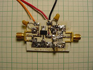
In the field of electronics, a bootstrap circuit is one where part of the output of an amplifier stage is applied to the input, so as to alter the input impedance of the amplifier. When applied deliberately, the intention is usually to increase rather than decrease the impedance. Generally, any technique where part of the output of a system is used at startup is described as bootstrapping.

Parasitic oscillation is an undesirable electronic oscillation in an electronic or digital device. It is often caused by feedback in an amplifying device. The problem occurs notably in RF, audio, and other electronic amplifiers as well as in digital signal processing. It is one of the fundamental issues addressed by control theory.

Distributed element circuit

Distributed element circuits are electrical circuits composed of lengths of transmission lines or other distributed components. These circuits perform the same functions as conventional circuits composed of passive components, such as capacitors, inductors, and transformers. They are used mostly at microwave frequencies, where conventional components are difficult to implement.

References

  1. W. S. Percival, “Thermionic Valve Circuits,” British Patent Specification no. 460,562, filed 24 July 1936, granted January 1937.
  2. E. L. Ginzton; W. R. Hewlett; J. H. Jasberg; J. D. Noe (1948). "Distributed Amplification". Proc. IRE: 956–69. doi:10.1109/JRPROC.1948.231624.
  3. E. W. Strid; K. R. Gleason (1982). "A DC-12 GHz Monolithic GaAsFET Distributed Amplifier". IEEE Transactions on Microwave Theory and Techniques. 30 (7): 969–975. doi:10.1109/TMTT.1982.1131185.
  4. Y. Ayasli; R. L. Mozzi; J. L. Vorhaus; L. D. Reynolds; R. A. Pucel (1982). "A Monolithic GaAs 1-13-GHz Traveling-Wave Amplifier". IEEE Transactions on Microwave Theory and Techniques. 30 (7): 976–981. doi:10.1109/TMTT.1982.1131186.
  5. K. B. Niclas; W. T. Wilser; T. R. Kritzer; R. R. Pereira (1983). "On Theory and Performance of Solid-State Microwave Distributed Amplifiers". IEEE Transactions on Microwave Theory and Techniques. 31 (6): 447–456. doi:10.1109/TMTT.1983.1131524.
  6. R. Majidi-Ahy; C. K. Nishimoto; M. Riaziat; M. Glenn; S. Silverman; S.-L. Weng; Y.-C. Pao; G. A. Zdasiuk; S. G. Bandy; Z. C. H. Tan (1990). "Coplanar Waveguide". IEEE Transactions on Microwave Theory and Techniques. 38 (12): 1986. doi:10.1109/22.64584.
  7. S. Kimura; Y. Imai; Y. Umeda; T. Enoki (1996). "Loss-compensated Distributed Baseband Amplifier for Optical Transmission Systems". IEEE Transactions on Microwave Theory and Techniques. 44 (10): 1688–1693. doi:10.1109/22.538960.
  8. D. Linten; S. Thijs; W. Jeamsaksiri; J. Ramos; A. Mercha; M. I. Natarajan; P. Wambacq; A. J. Scholten; S. Decoutere (July 16–18, 2005). "An Integrated 5 GHz Low-Noise Amplifier with 5.5 kV HBM ESD protection in 90 nm RF CMOS". Symp. on VLSI Circuits Digest of Technical Papers: 86–89..