Since the arc is contained within the interrupter, switchgear using vacuum interrupters are very compact compared with switchgear using air, sulfur hexafluoride (SF6) or oil as arc-suppression medium. Vacuum interrupters can be used for circuit-breakers and load switches. Circuit-breaker vacuum interrupters are used primarily in the power sector in substation and power-generation facilities, and load-switching vacuum interrupters are used for power-grid end users.
History
The use of a vacuum for switching electrical currents was motivated by the observation that a one-centimeter gap in an X-ray tube could withstand tens of thousands of volts. Although some vacuum switching devices were patented during the 19th century, they were not commercially available. In 1926, a group led by Royal Sorensen at the California Institute of Technology investigated vacuum switching and tested several devices; fundamental aspects of arc interruption in a vacuum were investigated. Sorenson presented the results at an AIEE meeting that year, and predicted the switches' commercial use. In 1927, General Electric purchased the patent rights and began commercial development. The Great Depression and the development of oil-filled switchgear caused the company to reduce development work, and little commercially important work was done on vacuum power switchgear until the 1950s.[1]
In 1956, Hugh C. Ross at Jennings Radio Manufacturing Corporation revolutionized the high-frequency-circuit vacuum switch and produced a vacuum switch with a rating of 15 kV at 200 A. Five years later, Thomas H. Lee at General Electric produced the first vacuum circuit breakers[2][3] with a rated voltage of 15 kV at short-circuit breaking currents of 12.5 kA. In 1966, devices were developed with a rated voltage of 15 kV and short-circuit breaking currents of 25 and 31.5 kA. After the 1970s, vacuum switches began to replace the minimal-oil switches in medium-voltage switchgear. In the early 1980s, SF6 switches and breakers were also gradually replaced by vacuum technology in medium-voltage application.
As of 2018, a vacuum circuit-breaker had reached 145 kV with a short-circuit rating of 200 kA.[4] In 2019, a research team in China tested a vacuum high-voltage circuit-breaker with 12 interrupters, for a rated voltage of 363 kV and a short-circuit rating of 63 kA.[5]
Classification
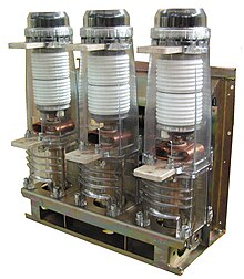
A medium-voltage three-phase vacuum circuit breaker with three vacuum-interrupter housings
Vacuum interrupters may be classified by enclosure type, by application, and by voltage class.
Experimental, radio-frequency, and early power-switching vacuum interrupters had glass enclosures. More recently, vacuum interrupters for power switchgear are made with ceramic envelopes.
Applications and uses include circuit-breakers, generator circuit-breaker, load switches, motor contactors, and reclosers. Special-purpose vacuum interrupters are also manufactured, such as those used in transformertap changers or in electrical arc furnaces.
Generator circuit-breaker
Research and investigation in the early 1990s allowed the employment of vacuum switching technology for generator applications. Generator switching applications are well known for their higher strains on interrupting devices, such as high fault current of high asymmetry or high and steep transient recovery voltage; the standard IEC/IEEE 62271-37-013 (former and still valid IEEE C37.013, 1997) was introduced to address such requirements on circuit-breakers used in generator applications.
Vacuum circuit-breakers can be qualified as a generator circuit-breakers (GCB) according to IEC/IEEE 62271-37-013. Compared to circuit-breakers using other quenching media (such as SF6, air-blast or minimum oil), vacuum circuit-breakers have the advantages of:
Great recovery strength, eliminating the need for capacitors to reduce the steepness of the transient recovery voltage (as required in most SF6 generator circuit-breakers);
High mechanical and electrical durability with significantly higher numbers and frequency of possible switching operations without maintenance; and
Environmental-friendliness by not using SF6.
Vacuum GCBs are suitable for frequent switching duty and for interrupting low-frequency currents as found in pumped storage power plants.[6]
Structure
A vacuum interrupter generally has one fixed and one moving contact, a flexible bellows to allow movement of that contact, and arc shields enclosed in a hermetically-sealed glass, ceramic or metal housing with a high vacuum. The moving contact is connected by a flexible braid to the external circuit, and is moved by a mechanism when the device is required to open or close. Since air pressure tends to close the contacts, the operating mechanism must hold the contacts open against the closing force of air pressure on the bellows.
Airtight enclosure
The interrupter's enclosure is made of glass or ceramic. Hermetic seals ensure that the interrupter vacuum is maintained for the life of the device. The enclosure must be impermeable to gas, and must not give off trapped gas. The stainless-steel bellows isolates the vacuum inside the interrupter from the external atmosphere and moves the contact within a specified range, opening and closing the switch.
Shielding
A vacuum interrupter has shields around the contacts and at the ends of the interrupter, preventing any contact material vaporized during an arc from condensing on the inside of the vacuum envelope. This would reduce the insulation strength of the envelope, ultimately resulting in the arcing of the interrupter when open. The shield also helps control the shape of the electric-field distribution inside the interrupter, contributing to a higher open-circuit voltage rating. It helps absorb some of the energy produced in the arc, increasing a device's interrupting rating.
Contacts
30 year old Siemens vacuum interrupter
The contacts carry the circuit current when closed, forming the terminals of the arc when open. They are made of a variety of materials, depending on the vacuum interrupter's use and design for long contact life, rapid recovery of voltage withstand rating, and control of overvoltage due to current chopping.
An external operating mechanism drives the moving contact, which opens and closes the connected circuit. The vacuum interrupter includes a guide sleeve to control the moving contact and protect the sealing bellows from twisting, which would drastically shorten its life.
Although some vacuum-interrupter designs have simple butt contacts, contacts are generally shaped with slots, ridges, or grooves to improve their ability to break high currents. Arc current flowing through the shaped contacts generate magnetic forces on the arc column, which cause the arc contact spot to move rapidly over the surface of the contact. This reduces contact wear due to erosion by an arc, which melts the contact metal at the point of contact.
Only a few manufacturers of vacuum interrupters worldwide produce the contact material itself. The basic raw materials, copper and chromium, are combined into the contact material by means of an arc-melting procedure. Contact materials require the following:
In circuit-breakers, vacuum interrupter contact materials are primarily a 50-50 copper-chromium alloy. They may be made by welding a copper–chromium alloy sheet on the upper and lower contact surfaces over a contact seat made of oxygen-free copper. Other materials, such as silver, tungsten and tungsten compounds, are used in other interrupter designs. The vacuum interrupter's contact materials has a great influence on its breaking capacity, electrical durability and level of current chopping. The contact structure, or design, of a vacuum interrupter also affects the breaking capacity and the breakdown voltage curve during operation. The main contact structures are radial magnetic field (RMF) also named transverse magnetic field (TMF), axial magnetic field (AMF) and contact discs (or butt shaped), with the slotted AMF discs deburred at the end.[7]
Bellows
The vacuum interrupter bellows allows the moving contact to be operated from outside the interrupter enclosure, and must maintain a long-term high vacuum over the expected operating life of the interrupter. The bellows is made of stainless steel with a thickness of 0.1 to 0.2mm. Its fatigue life is affected by heat conducted from the arc.
To enable them to meet the requirements for high endurance in real practice, the bellows are regularly subjected to an endurance test every three months. The test is carried out in a fully automatic test cabin with the travels adjusted to the respective type.
Bellows lifetime are over 30,000 CO operation cycles.
Operation
A vacuum interrupter uses a high vacuum to extinguish the arc between a pair of contacts. As the contacts move apart, current flows through a smaller area. There is a sharp increase in resistance between the contacts, and the temperature at the contact surface increases rapidly until the occurrence of electrode-metal evaporation. At the same time, the electric field is very high across the small contact gap. The breakdown of the gap produces a vacuum arc. As the alternating current is forced to pass through zero thanks to the arc resistance, and the gap between the fixed and moving contacts widens, the conductive plasma produced by the arc moves away from the gap and becomes non-conductive. The current is interrupted.
AMF and RMF contacts have spiral (or radial) slots cut into their faces. The shape of the contacts produces magnetic forces which move the arc spot over the surface of the contacts, so the arc does not remain in one place for very long. The arc is evenly distributed over the contact surface to maintain a low arc voltage and to reduce contact erosion.
Production process
Components of the vacuum interrupter must be thoroughly cleaned before assembly, since contaminants could emit gas into the vacuum envelope. To ensure a high breakdown voltage, components are assembled in a cleanroom where dust is strictly controlled.
After the surfaces have been finished and cleaned by electroplating and an optical inspection of the surface consistency of all single parts has been performed, the interrupter is assembled. High-vacuum solder is applied at the joints of the components, the parts are aligned, and the interrupters are fixed. As cleanliness during assembly is especially important, all operations are done under air-conditioned clean-room conditions. In this way the manufacturer can guarantee a constantly high quality of the interrupters and maximum possible ratings up to 100 kA according to IEC/IEEE 62271-37-013.
Subassemblies of vacuum interrupters were initially assembled and brazed together in a hydrogen-atmosphere furnace. A tube connected to the interrupter's interior was used to evacuate the interrupter with an external vacuum pump while the interrupter was maintained at about 400°C (752°F). Since the 1970s, interrupter subcomponents have been assembled in a high-vacuum brazing furnace by a combined brazing-and-evacuation process. Tens (or hundreds) of bottles are processed in one batch, using a high-vacuum furnace that heats them at temperatures up to 900°C and a pressure of 10−6 mbar.[8] Thus, the interrupters fulfill the quality requirement "sealed for lifetime". Thanks to the fully automatic production process, the high quality can be constantly reproduced at any time
Then, the evaluation of the interrupters by means of the X-ray procedure is used to verify the positions as well as the completeness of the internal components, and the quality of the brazing points. It ensures the high quality of vacuum interrupters.
During forming, the definitive internal dielectric strength of the vacuum interrupter is established with gradually increasing voltage, and this is verified by a subsequent lightning impulse voltage test. Both operations are done with higher values than those specified in the standards, as evidence of the quality of the vacuum interrupters. This is the prerequisite for long endurance and high availability.
Sealed for lifetime
Due to their manufacturing process,[9] vacuum interrupters are proved to be "sealed for lifetime".[10] This avoids the need for monitoring systems or tightness tests as stated in the IEEE std C37.100.1 on paragraph 6.8.3.[11]
Overvoltage effects
Under certain circumstances, the vacuum circuit breaker can force the current in the circuit to zero before the natural zero (and reversal of current) in the alternating-current circuit. If interrupter operation timing is unfavorable with respect to the AC-voltage waveform (when the arc is extinguished but the contacts are still moving and ionization has not yet dissipated in the interrupter), the voltage may exceed the gap's withstand voltage. This can re-ignite the arc, causing abrupt transient currents. In either case, oscillation is introduced into the system that may result in significant overvoltage. Vacuum-interrupter manufacturers address these concerns by selecting contact materials and designs to minimize current chopping. To protect equipment from overvoltage, vacuum switchgear usually includes surge arresters.[12]
Nowadays, with very low current chopping, vacuum circuit breakers will not induce an overvoltage that could reduce insulation from surrounding equipment.
References
↑ Allan Greenwood, Vacuum Switchgear, IET, 1994 ISBN0852968558, chapter 1.
↑ Robert W. Smeaton, William H. Ubert, Switchgear and Control Handbook, 3rd Edition, McGraw Hill, 1998, pages 14-29 and 14-30
This page is based on this Wikipedia article Text is available under the CC BY-SA 4.0 license; additional terms may apply. Images, videos and audio are available under their respective licenses.