In electronics, the figures of merit of an amplifier are numerical measures that characterize its properties and performance. Figures of merit can be given as a list of specifications that include properties such as gain, bandwidth, noise and linearity, among others listed in this article. Figures of merit are important for determining the suitability of a particular amplifier for an intended use.

An amplifier, electronic amplifier or (informally) amp is an electronic device that can increase the magnitude of a signal. It is a two-port electronic circuit that uses electric power from a power supply to increase the amplitude of a signal applied to its input terminals, producing a proportionally greater amplitude signal at its output. The amount of amplification provided by an amplifier is measured by its gain: the ratio of output voltage, current, or power to input. An amplifier is defined as a circuit that has a power gain greater than one.

An operational amplifier is a DC-coupled high-gain electronic voltage amplifier with a differential input and, usually, a single-ended output. In this configuration, an op amp produces an output potential that is typically 100,000 times larger than the potential difference between its input terminals. The operational amplifier traces its origin and name to analog computers, where they were used to perform mathematical operations in linear, non-linear, and frequency-dependent circuits.

In electronics, a comparator is a device that compares two voltages or currents and outputs a digital signal indicating which is larger. It has two analog input terminals and and one binary digital output . The output is ideally

A negative-feedback amplifier is an electronic amplifier that subtracts a fraction of its output from its input, so that negative feedback opposes the original signal. The applied negative feedback can improve its performance and reduces sensitivity to parameter variations due to manufacturing or environment. Because of these advantages, many amplifiers and control systems use negative feedback.

An instrumentation amplifier is a type of differential amplifier that has been outfitted with input buffer amplifiers, which eliminate the need for input impedance matching and thus make the amplifier particularly suitable for use in measurement and test equipment. Additional characteristics include very low DC offset, low drift, low noise, very high open-loop gain, very high common-mode rejection ratio, and very high input impedances. Instrumentation amplifiers are used where great accuracy and stability of the circuit both short- and long-term are required.

A differential amplifier is a type of electronic amplifier that amplifies the difference between two input voltages but suppresses any voltage common to the two inputs. It is an analog circuit with two inputs and and one output , in which the output is ideally proportional to the difference between the two voltages:

A buffer amplifier is one that provides electrical impedance transformation from one circuit to another, with the aim of preventing the signal source from being affected by whatever currents that the load may impose. The signal is 'buffered from' load currents. Two main types of buffer exist: the voltage buffer and the current buffer.

In electronics, a common-emitter amplifier is one of three basic single-stage bipolar-junction-transistor (BJT) amplifier topologies, typically used as a voltage amplifier. It offers high current gain, medium input resistance and a high output resistance. The output of a common emitter amplifier is 180 degrees out of phase to the input signal.

In electronics, slew rate is defined as the change of voltage or current, or any other electrical quantity, per unit of time. Expressed in SI units, the unit of measurement is volts/second or amperes/second, but is usually expressed in terms of microseconds (μs) or nanoseconds (ns).
This article illustrates some typical operational amplifier applications. A non-ideal operational amplifier's equivalent circuit has a finite input impedance, a non-zero output impedance, and a finite gain. A real op-amp has a number of non-ideal features as shown in the diagram, but here a simplified schematic notation is used, many details such as device selection and power supply connections are not shown. Operational amplifiers are optimised for use with negative feedback, and this article discusses only negative-feedback applications. When positive feedback is required, a comparator is usually more appropriate. See Comparator applications for further information.
A Norton amplifier or current differencing amplifier (CDA) is an electronic amplifier with two low impedance current inputs and one low impedance voltage output where the output voltage is proportional to the difference between the two input currents. A norton amplifier is a current controlled voltage source (CCVS) controlled by the difference of two input currents.

A charge amplifier is an electronic current integrator that produces a voltage output proportional to the integrated value of the input current, or the total charge injected.

The operational transconductance amplifier (OTA) is an amplifier whose differential input voltage produces an output current. Thus, it is a voltage controlled current source (VCCS). There is usually an additional input for a current to control the amplifier's transconductance. The OTA is similar to a standard operational amplifier in that it has a high impedance differential input stage and that it may be used with negative feedback.
A balanced circuit is circuitry for use with a balanced line or the balanced line itself. Balanced lines are a common method of transmitting many types of electrical communication signals between two points on two wires. In a balanced line the two signal lines are of a matched impedance to help ensure that interference induced in the line is common-mode and can be removed at the receiving end by circuitry with good common-mode rejection. To maintain the balance, circuit blocks which interface to the line, or are connected in the line, must also be balanced.
Technical specifications and detailed information on the valve audio amplifier, including its development history.
The Miller theorem refers to the process of creating equivalent circuits. It asserts that a floating impedance element, supplied by two voltage sources connected in series, may be split into two grounded elements with corresponding impedances. There is also a dual Miller theorem with regards to impedance supplied by two current sources connected in parallel. The two versions are based on the two Kirchhoff's circuit laws.
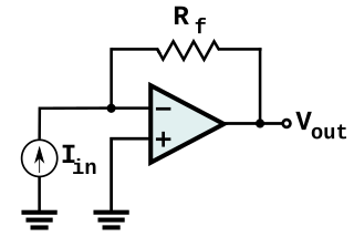
In electronics, a transimpedance amplifier (TIA) is a current to voltage converter, almost exclusively implemented with one or more operational amplifiers. The TIA can be used to amplify the current output of Geiger–Müller tubes, photo multiplier tubes, accelerometers, photo detectors and other types of sensors to a usable voltage. Current to voltage converters are used with sensors that have a current response that is more linear than the voltage response. This is the case with photodiodes where it is not uncommon for the current response to have better than 1% nonlinearity over a wide range of light input. The transimpedance amplifier presents a low impedance to the photodiode and isolates it from the output voltage of the operational amplifier. In its simplest form a transimpedance amplifier has just a large valued feedback resistor, Rf. The gain of the amplifier is set by this resistor and because the amplifier is in an inverting configuration, has a value of -Rf. There are several different configurations of transimpedance amplifiers, each suited to a particular application. The one factor they all have in common is the requirement to convert the low-level current of a sensor to a voltage. The gain, bandwidth, as well as current and voltage offsets change with different types of sensors, requiring different configurations of transimpedance amplifiers.

The current-feedback operational amplifier is a type of electronic amplifier whose inverting input is sensitive to current, rather than to voltage as in a conventional voltage-feedback operational amplifier (VFA). The CFA was invented by David Nelson at Comlinear Corporation, and first sold in 1982 as a hybrid amplifier, the CLC103. An early patent covering a CFA is U.S. Patent 4,502,020, David Nelson and Kenneth Saller. The integrated circuit CFAs were introduced in 1987 by both Comlinear and Elantec. They are usually produced with the same pin arrangements as VFAs, allowing the two types to be interchanged without rewiring when the circuit design allows. In simple configurations, such as linear amplifiers, a CFA can be used in place of a VFA with no circuit modifications, but in other cases, such as integrators, a different circuit design is required. The classic four-resistor differential amplifier configuration also works with a CFA, but the common-mode rejection ratio is poorer than that from a VFA.

The NE5532, also sold as SA5532, SE5532 and NG5532 is a dual monolithic, bipolar, internally compensated operational amplifier for audio applications introduced by Signetics in 1979. The 5532 and the contemporary TL072 were the first operational amplifiers that outperformed discrete class A circuits in professional audio applications. Due to low noise and very low distortion, the 5532 became the industry standard for professional audio. According to Douglas Self, "there is probably no music on the planet that has not passed through a hundred or more 5532s on its way to the consumer". The performance of the 5532 remained best in class for almost thirty years, until the introduction of the LM4562 in 2007. As of 2021, the 5532 remains in mass production as a generic product.


