A satellite modem or satmodem is a modem used to establish data transfers using a communications satellite as a relay. A satellite modem's main function is to transform an input bitstream to a radio signal and vice versa.
There are some devices that include only a demodulator (and no modulator, thus only allowing data to be downloaded by satellite) that are also referred to as "satellite modems." These devices are used in satellite Internet access (in this case uploaded data is transferred through a conventional PSTN modem or an ADSL modem).
A satellite modem is not the only device needed to establish a communication channel. Other equipment that is essential for creating a satellite link include satellite antennas and frequency converters.
Data to be transmitted are transferred to a modem from data terminal equipment (e.g. a computer). The modem usually has intermediate frequency (IF) output (that is, 50-200 MHz), however, sometimes the signal is modulated directly to L band. In most cases, frequency has to be converted using an upconverter before amplification and transmission.
A modulated signal is a sequence of symbols, pieces of data represented by a corresponding signal state, e.g. a bit or a few bits, depending upon the modulation scheme being used. Recovering a symbol clock (making a local symbol clock generator synchronous with the remote one) is one of the most important tasks of a demodulator.
Similarly, a signal received from a satellite is firstly downconverted (this is done by a Low-noise block converter - LNB), then demodulated by a modem, and at last handled by data terminal equipment. The LNB is usually powered by the modem through the signal cable with 13 or 18 V DC.
Features
The main functions of a satellite modem are modulation and demodulation. Satellite communication standards also define error correction codes and framing formats.
Popular modulation types being used for satellite communications:
Probably the best way of understanding how a modem works is to look at its internal structure. A block diagram of a generic satellite modem is shown on the image.
The purpose of the analog tract in the receiver is to convert signal's frequency, to adjust its power via an automatic gain control circuit and to get its complex envelope components.
The input signal for the analog tract is at the intermediate frequency, sometimes, in the L band, in which case it must be converted to an IF. Then the signal is either sampled or processed by the four-quadrant multiplier which produces the complex envelope components (I, Q) through multiplying it by the heterodyne frequency (see superheterodyne receiver).
A digital modulator transforms a digital stream into a radio signal at the intermediate frequency (IF). A modulator is generally simpler than a demodulator because it doesn't have to recover symbol and carrier frequencies.
A demodulator is one of the most important parts of the receiver. The exact structure of the demodulator is defined by a modulation type. However, the fundamental concepts are similar. Moreover, it is possible to develop a demodulator that can process signals with different modulation types.
Digital demodulation implies that a symbol clock (and, in most cases, an intermediate frequency generator) at the receiving side has to be synchronous with those at the transmitting side. This is achieved by the following two circuits:
timing recovery circuit, determining the borders of symbols;
carrier recovery circuit, which determines the actual meaning of each symbol. There are modulation types (like frequency-shift keying) that can be demodulated without carrier recovery, however, this method, known as noncoherent demodulation, is generally worse.
Error correction techniques are essential for satellite communications, because, due to satellite's limited power a signal-to-noise ratio at the receiver is usually rather poor. Error correction works by adding an artificial redundancy to a data stream at the transmitting side and using this redundancy to correct errors caused by noise and interference. This is performed by an FEC encoder. The encoder applies an error correction code to the digital stream, thereby adding redundancy.
An FEC decoder decodes the Forward error correction code used within the signal. For example, the Digital Video Broadcasting standard defines a concatenated code consisting of inner convolutional (standard NASA code, punctured, with rates , , , , ), interleaving and outer Reed–Solomon code (block length: 204 bytes, information block: 188 bytes, can correct up to 8 bytes in the block).
There are several modulation types (such as PSK and QAM) that have a phase ambiguity, that is, a carrier can be restored in different ways. Differential coding is used to resolve this ambiguity.
When differential coding is used, the data are deliberately made to depend not only on the current symbol, but also on the previous one.
Scrambling is a technique used to randomize a data stream to eliminate long '0'-only and '1'-only sequences and to assure energy dispersal. Long '0'-only and '1'-only sequences create difficulties for timing recovery circuit. Scramblers and descramblers are usually based on linear-feedback shift registers.
A scrambler randomizes the transmitted data stream. A descrambler restores the original stream from the scrambled one.
Scrambling shouldn't be confused with encryption, since it doesn't protect information from intruders.
Multiplexing
A multiplexer transforms several digital streams into one stream. This is often referred to as 'muxing.'
Generally, a demultiplexer is a device that transforms one multiplexed data stream into several. Satellite modems don't have many outputs, so a demultiplexer here performs a drop operation, allowing to the modem to choose channels that will be transferred to the output.
A demultiplexer achieves this goal by maintaining frame synchronization.
Applications
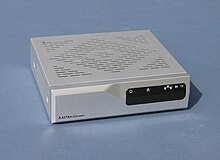
The NS3000 Satellite Modem modulates and demodulates data and video signals transmitted via satellite.The "IP modem" (satellite modem) developed and made by Newtec of Belgium for SES' 2Mbit/s ASTRA2Connect European two-way satellite Internet system
There are two different types, both employing the Digital Video Broadcasting (DVB) standard as their basis:
One-way satmodems (DVB-IP modems) use a return channel not based on communication with the satellite, such as telephone or cable.
Two-way satmodems (DVB-RCS modems, also called astromodems) employ a satellite-based return channel as well; they do not need another connection. DVB-RCS is ETSIstandardEN 301 790.
There are also industrial satellite modems intended to provide a permanent link. They are used, for example, in the Steel shankar network.
Modulation is defined as the process by which some characteristics like amplitude, frequency, and phase of a carrier signal are varied in accordance with a modulating wave.
In telecommunications, orthogonal frequency-division multiplexing (OFDM) is a type of digital transmission used in digital modulation for encoding digital (binary) data on multiple carrier frequencies. OFDM has developed into a popular scheme for wideband digital communication, used in applications such as digital television and audio broadcasting, DSL internet access, wireless networks, power line networks, and 4G/5G mobile communications.
Quadrature amplitude modulation (QAM) is the name of a family of digital modulation methods and a related family of analog modulation methods widely used in modern telecommunications to transmit information. It conveys two analog message signals, or two digital bit streams, by changing (modulating) the amplitudes of two carrier waves, using the amplitude-shift keying (ASK) digital modulation scheme or amplitude modulation (AM) analog modulation scheme. The two carrier waves are of the same frequency and are out of phase with each other by 90°, a condition known as orthogonality or quadrature. The transmitted signal is created by adding the two carrier waves together. At the receiver, the two waves can be coherently separated (demodulated) because of their orthogonality. Another key property is that the modulations are low-frequency/low-bandwidth waveforms compared to the carrier frequency, which is known as the narrowband assumption.
Delta modulation is an analog-to-digital and digital-to-analog signal conversion technique used for transmission of voice information where quality is not of primary importance. DM is the simplest form of differential pulse-code modulation (DPCM) where the difference between successive samples is encoded into n-bit data streams. In delta modulation, the transmitted data are reduced to a 1-bit data stream representing either up (↗) or down (↘). Its main features are:
Phase-shift keying (PSK) is a digital modulation process which conveys data by changing (modulating) the phase of a constant frequency carrier wave. The modulation is accomplished by varying the sine and cosine inputs at a precise time. It is widely used for wireless LANs, RFID and Bluetooth communication.
In telecommunications, a scrambler is a device that transposes or inverts signals or otherwise encodes a message at the sender's side to make the message unintelligible at a receiver not equipped with an appropriately set descrambling device. Whereas encryption usually refers to operations carried out in the digital domain, scrambling usually refers to operations carried out in the analog domain. Scrambling is accomplished by the addition of components to the original signal or the changing of some important component of the original signal in order to make extraction of the original signal difficult. Examples of the latter might include removing or changing vertical or horizontal sync pulses in television signals; televisions will not be able to display a picture from such a signal. Some modern scramblers are actually encryption devices, the name remaining due to the similarities in use, as opposed to internal operation.
Data communication, including data transmission and data reception, is the transfer of data, transmitted and received over a point-to-point or point-to-multipoint communication channel. Examples of such channels are copper wires, optical fibers, wireless communication using radio spectrum, storage media and computer buses. The data are represented as an electromagnetic signal, such as an electrical voltage, radiowave, microwave, or infrared signal.
Demodulation is extracting the original information-bearing signal from a carrier wave. A demodulator is an electronic circuit that is used to recover the information content from the modulated carrier wave. There are many types of modulation so there are many types of demodulators. The signal output from a demodulator may represent sound, images or binary data.
In telecommunications, node-to-node data transfer is the movement of data from one node of a network to the next. In the OSI model it is handled by the lowest two layers, the data link layer and the physical layer.
8VSB is the modulation method used for broadcast in the ATSC digital television standard. ATSC and 8VSB modulation is used primarily in North America; in contrast, the DVB-T standard uses COFDM.
DVB-T, short for Digital Video Broadcasting – Terrestrial, is the DVB European-based consortium standard for the broadcast transmission of digital terrestrial television that was first published in 1997 and first broadcast in Singapore in February, 1998. This system transmits compressed digital audio, digital video and other data in an MPEG transport stream, using coded orthogonal frequency-division multiplexing modulation. It is also the format widely used worldwide for Electronic News Gathering for transmission of video and audio from a mobile newsgathering vehicle to a central receive point. It is also used in the US by Amateur television operators.
Digital Video Broadcasting - Cable (DVB-C) is the DVB European consortium standard for the broadcast transmission of digital television over cable. This system transmits an MPEG-2 or MPEG-4 family digital audio/digital video stream, using a QAM modulation with channel coding. The standard was first published by the ETSI in 1994, and subsequently became the most widely used transmission system for digital cable television in Europe, Asia and South America. It is deployed worldwide in systems ranging from the larger cable television networks (CATV) down to smaller satellite master antenna TV (SMATV) systems.
In a digitally modulated signal or a line code, symbol rate, modulation rate or baud rate is the number of symbol changes, waveform changes, or signaling events across the transmission medium per unit of time. The symbol rate is measured in baud (Bd) or symbols per second. In the case of a line code, the symbol rate is the pulse rate in pulses per second. Each symbol can represent or convey one or several bits of data. The symbol rate is related to the gross bit rate, expressed in bits per second.
In computing, telecommunication, information theory, and coding theory, forward error correction (FEC) or channel coding is a technique used for controlling errors in data transmission over unreliable or noisy communication channels.
In radio, a detector is a device or circuit that extracts information from a modulated radio frequency current or voltage. The term dates from the first three decades of radio (1888-1918). Unlike modern radio stations which transmit sound on an uninterrupted carrier wave, early radio stations transmitted information by radiotelegraphy. The transmitter was switched on and off to produce long or short periods of radio waves, spelling out text messages in Morse code. Therefore, early radio receivers did not have to demodulate the radio signal, but just distinguish between the presence or absence of a radio signal, to reproduce the Morse code "dots" and "dashes". The device that performed this function in the receiver circuit was called a detector. A variety of different detector devices, such as the coherer, electrolytic detector, magnetic detector and the crystal detector, were used during the wireless telegraphy era until superseded by vacuum tube technology.
In digital communications, differential coding is a technique used to provide unambiguous signal reception when using some types of modulation. It makes data to be transmitted to depend not only on the current signal state, but also on the previous one.
A carrier recovery system is a circuit used to estimate and compensate for frequency and phase differences between a received signal's carrier wave and the receiver's local oscillator for the purpose of coherent demodulation.
GPS signals are broadcast by Global Positioning System satellites to enable satellite navigation. Receivers on or near the Earth's surface can determine location, time, and velocity using this information. The GPS satellite constellation is operated by the 2nd Space Operations Squadron (2SOPS) of Space Delta 8, United States Space Force.
A DTV receiver is a set-top box that permits the reception of digital television. Its components are very similar to a desktop PC. The DTV receiver is a vital link in the chain of television system. The goal of a broadcasting system is to concentrate the hardware requirements at the source to simplify the receivers and makes it as inexpensive as possible.
Generic Stream Encapsulation, or GSE for short, is a Data link layer protocol defined by DVB. GSE provides means to carry packet oriented protocols such as IP on top of uni-directional physical layers such as DVB-S2, DVB-T2 and DVB-C2.
This page is based on this Wikipedia article Text is available under the CC BY-SA 4.0 license; additional terms may apply. Images, videos and audio are available under their respective licenses.