Overview
A spacecraft's attitude must typically be stabilized and controlled for a variety of reasons. It is often needed so that the spacecraft high-gain antenna may be accurately pointed to Earth for communications, so that onboard experiments may accomplish precise pointing for accurate collection and subsequent interpretation of data, so that the heating and cooling effects of sunlight and shadow may be used intelligently for thermal control, and also for guidance: short propulsive maneuvers must be executed in the right direction.
Types of stabilization
Attitude control of spacecraft is maintained using one of two principal approaches:
- Spin stabilization Spin stabilization is accomplished by setting the spacecraft spinning, using the gyroscopic action of the rotating spacecraft mass as the stabilizing mechanism. Propulsion system thrusters are fired only occasionally to make desired changes in spin rate, or in the spin-stabilized attitude. If desired, the spinning may be stopped through the use of thrusters or by yo-yo de-spin. The Pioneer 10 and Pioneer 11 probes in the outer Solar System are examples of spin-stabilized spacecraft. [1]
- Three-axis stabilization is an alternative method of spacecraft attitude control in which the spacecraft is held fixed in the desired orientation without any rotation.
- One method is to use small thrusters to continually nudge the spacecraft back and forth within a deadband of allowed attitude error. Thrusters may also be referred to as mass-expulsion control (MEC) [2] systems, or reaction control systems (RCS). The space probes Voyager 1 and Voyager 2 employ this method, and have used up about three quarters [3] of their 100 kg of propellant as of July 2015.
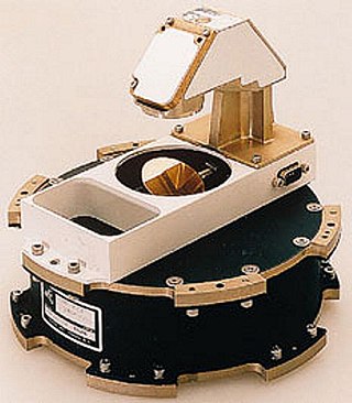
- Another method for achieving three-axis stabilization is to use electrically powered reaction wheels, also called momentum wheels, which are mounted on three orthogonal axes aboard the spacecraft. They provide a means to trade angular momentum back and forth between spacecraft and wheels. To rotate the vehicle on a given axis, the reaction wheel on that axis is accelerated in the opposite direction. To rotate the vehicle back, the wheel is slowed. Excess momentum that builds up in the system due to external torques from, for example, solar photon pressure or gravity gradients, must be occasionally removed from the system by applying controlled torque to the spacecraft to allowing the wheels to return to a desired speed under computer control. This is done during maneuvers called momentum desaturation or momentum unload maneuvers. Most spacecraft use a system of thrusters to apply the torque for desaturation maneuvers. A different approach was used by the Hubble Space Telescope, which had sensitive optics that could be contaminated by thruster exhaust, and instead used magnetic torquers for desaturation maneuvers.
There are advantages and disadvantages to both spin stabilization and three-axis stabilization. Spin-stabilized craft provide a continuous sweeping motion that is desirable for fields and particles instruments, as well as some optical scanning instruments, but they may require complicated systems to de-spin antennas or optical instruments that must be pointed at targets for science observations or communications with Earth. Three-axis controlled craft can point optical instruments and antennas without having to de-spin them, but they may have to carry out special rotating maneuvers to best utilize their fields and particle instruments. If thrusters are used for routine stabilization, optical observations such as imaging must be designed knowing that the spacecraft is always slowly rocking back and forth, and not always exactly predictably. Reaction wheels provide a much steadier spacecraft from which to make observations, but they add mass to the spacecraft, they have a limited mechanical lifetime, and they require frequent momentum desaturation maneuvers, which can perturb navigation solutions because of accelerations imparted by the use of thrusters.[ citation needed ]
Articulation
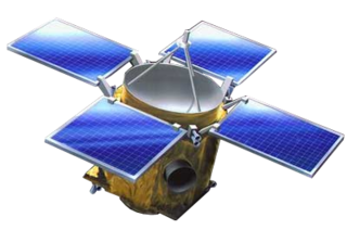
Many spacecraft have components that require articulation. Voyager and Galileo , for example, were designed with scan platforms for pointing optical instruments at their targets largely independently of spacecraft orientation. Many spacecraft, such as Mars orbiters, have solar panels that must track the Sun so they can provide electrical power to the spacecraft. Cassini's main engine nozzles were steerable. Knowing where to point a solar panel, or scan platform, or a nozzle — that is, how to articulate it — requires knowledge of the spacecraft's attitude. Because a single subsystem keeps track of the spacecraft's attitude, the Sun's location, and Earth's location, it can compute the proper direction to point the appendages. It logically falls to the same subsystem – the Attitude and Articulation Control Subsystem (AACS), then, to manage both attitude and articulation. The name AACS may even be carried over to a spacecraft even if it has no appendages to articulate. [4]
Geometry
Attitude is part of the description of how an object is placed in the space it occupies. Attitude and position fully describe how an object is placed in space. (For some applications such as in robotics and computer vision, it is customary to combine position and attitude together into a single description known as Pose.)
Attitude can be described using a variety of methods; however, the most common are Rotation matrices, Quaternions, and Euler angles. While Euler angles are oftentimes the most straightforward representation to visualize, they can cause problems for highly-maneuverable systems because of a phenomenon known as Gimbal lock. A rotation matrix, on the other hand, provides a full description of the attitude at the expense of requiring nine values instead of three. The use of a rotation matrix can lead to increased computational expense and they can be more difficult to work with. Quaternions offer a decent compromise in that they do not suffer from gimbal lock and only require four values to fully describe the attitude.