Yaw bearing

Last updated
Schematic representation of the main wind turbine components. The yaw system is located between the wind turbine nacelle and tower. Wind.turbine.components.and.coordinates.svg
Schematic representation of the main wind turbine components. The yaw system is located between the wind turbine nacelle and tower.

The yaw bearing is the most crucial and cost intensive component of a yaw system found on modern horizontal axis wind turbines. The yaw bearing must cope with enormous static and dynamic loads and moments during the wind turbine operation, and provide smooth rotation characteristics for the orientation of the nacelle under all weather conditions. It has also to be corrosion and wear resistant and extremely long lasting. It should last for the service life of the wind turbine) while being cost effective.

Contents

History

Windmills of the 18th century began implementing rotatable nacelles to capture wind coming from different directions. The yaw systems of these "primitive" windmills were surprisingly similar to the ones on modern wind turbines. The nacelles rotated by means of wind driven yaw drives known as fantails, or by animal power, and were mounted on the windmill towers by means of an axial gliding bearing.

Historical.gliding.yaw.bearing.lock.png
Schematic representation of a historical gliding pad and lock configuration [1] next to...
Gliding.yaw.bearing.lock.png
a schematic of a similar configuration found on a modern wind turbine.

These gliding bearings consisted of multiple gliding blocks fixed on the windmill tower structure. These blocks maintained sliding contact with a gliding ring on the nacelle. The gliding blocks were wooden cube-like pieces with convex gliding surface covered with animal fat, or even lined with copper (or brass) sheet as a friction reduction means. These wooden blocks were fixed in wooden slots, carved in the wooden bearing substructure, by means of nails or wedges and were carefully leveled to create a flat surface where the nacelle gliding ring could glide. The gliding blocks, despite the lubrication would wear quite often and would have to be exchanged. This operation was relatively simple due to the wedge-based connection between substructure and gliding blocks. The gliding blocks were further locked via movable locking devices [1] which, in a different form, remain as a technical solution in modern gliding yaw bearings.

The gliding ring of the windmill nacelle was made from multiple wooden parts and, despite the old construction techniques, was usually quite level, allowing the nacelle to rotate smoothly around the tower axis. [1]

The hybrid yaw bearing system combines the solutions old windmills used. This system comprises multiple removable radial gliding pads in combination with an axial roller bearing. [1]

Schematic representation of a historical hybrid yaw bearing with axial rollers and radial gliding pads. Historical.hybrid.bearing.png
Schematic representation of a historical hybrid yaw bearing with axial rollers and radial gliding pads.

Types

The main categories of yaw bearings are:

Roller yaw bearing

Schematic representation of a typical roller yaw bearing configuration of a modern wind turbine. Roller.yaw.bearing.svg
Schematic representation of a typical roller yaw bearing configuration of a modern wind turbine.

The roller yaw bearing is a common technical yaw bearing solution followed by many wind turbine manufacturers as it offers low turning friction and smooth rotation of the nacelle. The low turning friction permits the implementation of slightly smaller yaw drives (compared to the gliding bearing solution), but on the other hand requires a yaw braking system.

Some manufacturers use a plurality of smaller yaw drives (usually six) to facilitate easy replacement. Such a configuration with plurality of yaw drives often offers the possibility of active yaw braking using differential torque from the yaw drives. In this case half of the yaw drives apply a small amount of torque for clockwise rotation and the other half apply torque in the opposite direction and then activate the internal magnetic brakes of the electric motor. In this way the pinion-gear rim backlash is eliminated and the nacelle is fixed in place.

Gliding yaw bearing

Schematic representation of the components of a modern gliding yaw bearing. Gliding.yaw.bearing.components.svg
Schematic representation of the components of a modern gliding yaw bearing.
Schematic representation of a typical gliding yaw bearing configuration of a modern wind turbine. Gliding.yaw.bearing.svg
Schematic representation of a typical gliding yaw bearing configuration of a modern wind turbine.

The gliding yaw bearing is a combined axial and radial bearing, which serves as a rotatable connection of the wind turbine nacelle and the tower. Contrary to the old windmill concept, the modern yaw bearings support the nacelle also from the top[ clarification needed ] thus restraining the nacelle from being rotated by the Y-axis due to the moments induced by the upper half of the rotor sweep disk and the X-axis due to the torque of the drive train (i.e. rotor, shaft, generator, etc. ).

Principally, the simplest way to accomplish the yaw bearing tasks with gliding elements is with two gliding planes for the axial loads (top and bottom) and a radial gliding surface for the radial loads. Consequently, the gliding yaw bearing comprises three general surfaces covered with multiple gliding pads. These gliding pads come in sliding contact with a steel disk, which is usually equipped with gear teeth to form a gliding-disk/gear-rim. The teeth may be located at the inner or the outer cylindrical face of the disk, while the arrangement of the gliding pads and their exact number and location vary strongly among the existing designs. To assemble the gliding yaw bearings, their cages split in several segments that are assembled together during wind turbine installation or manufacturing.

In its simplest form, the gliding yaw bearing uses pads (usually made out of polymers) distributed around the three contact surfaces to provide a proper guiding system for the radial and axial movement with relatively low friction coefficient. Such systems are economical and very robust but do not allow individual adjustment of the axial and radial gliding elements. This function importantly minimizes the axial and radial "play" of the gliding bearing due to manufacturing tolerances as well as due to wear of the gliding pads during operation.

To solve this problem, yaw systems incorporate pre-tensioned gliding bearings. These bearings have gliding pads that are pressed via pressure elements against the gliding disk to stabilize the nacelle against undesirable movement. The pressure elements can be simple steel springs, pneumatic, or hydraulic pre-tension elements, etc. The use of pneumatic or hydraulic pre-tension elements allows active control of the yaw bearing pre-tension, which provides yaw brake function.

Wear and lubrication

In all gliding bearings wear is an issue of concern, as well as lubrication. Conventional gliding yaw bearings incorporate gliding elements manufactured out of polymer plastics such as polyoxymethylene plastic (POM) or polyamide (PA). To reduce friction, wear, and avoid stick-slip effects (often present in such high friction slow moving systems), lubrication is often introduced. This solution generally solves the gliding issues, but introduces more components to the systems and increases the general complication (e.g., difficult maintenance procedures for removal of used lubricant). Some wind turbine manufacturers now use self lubricating gliding elements instead of a central lubrication system. These gliding elements are manufactured from low friction materials or composites (e.t.g polytetrafluoroethylene (Teflon)) that allow reliable operation of dry (non-lubricated) gliding yaw systems.

Maintenance and repair

Despite the fact that the gliding yaw bearings and their components are designed and constructed to last the service life of the wind turbine, it should be possible to replace worn out yaw bearing gliding elements or other components of the yaw system. To allow for replace-ability of worn out components, the yaw systems are designed in segments. Usually one or more gliding planes comprise several sub-elements that contain a number of gliding elements (radial or axial or a combination). These sub-elements can be individually removed and repaired, re-fit or replaced. In this way the yaw bearing can be serviced without the need of dis-assembly of the whole gliding yaw bearing (e.g., in case of a roller yaw bearing, dis-assembly of the whole wind turbine). This rep-arability offered by the segmented design of the gliding yaw bearing is one of the most important advantages of this system against the roller yaw bearing solution.

The only remaining issue is the replacement of the gliding elements of the gliding yaw bearing surface, which is not segmented. This is usually the top axial surface of the gliding bearing, which constantly supports the weight of the whole nacelle-rotor assembly. For the gliding elements of this gliding surface to be replaced, the nacelle-rotor assembly must be lifted by an external crane. An alternative solution to this problem is the use of mechanical or hydraulic jacks able to partially or fully lift the nacelle-rotor assembly while the gliding yaw bearing is still in place. In this way and by providing a small clearance between the gliding elements and the gliding disk, it is possible to exchange the sliding elements without dismantling the gliding yaw bearing.

Bearing Adjustment

Detailed view of a typical pre-tension system for an azimuth (yaw) gliding bearing of a modern wind turbine. Yaw.bearing.details.svg
Detailed view of a typical pre-tension system for an azimuth (yaw) gliding bearing of a modern wind turbine.

When the wind turbine nacelle is positioned on the tower and the yaw bearing assembly is completed it is necessary to adjust the pressure on the individual gliding pads of the bearing. This is necessary in order to avoid un-even wear of the gliding pads and excessive loading on some sectors of the yaw bearing. In order to achieve that, an adjustment mechanism is necessary, which enables the technicians to adjust the contact pressure of each individual gliding element in a controllable and secure way. The most common solution is the utilization of bottom bearing plates equipped with large opening, which accommodate the adjustable gliding bearing systems. These adjustable gliding bearings comprise a gliding unit (i.e. gliding pad) and an adjustable pressure distribution plate. In between the gliding pad and the pressure plate several spring (pre-tension) elements are located. The vertical position of the pressure plates is usually controlled by an adjustment screw. This adjustment screw presses against the pressure plate while being retained by a counter-pressure support plate, fixed on the bearing assembly with strong bolts. In this way it is possible to apply various levels of contact pressure among the different gliding pads and therefore to ensure that each gliding component of the yaw bearing arrangement is performing as anticipated.

See also

Related Research Articles

<span class="mw-page-title-main">Ball bearing</span> Type of rolling-element bearing

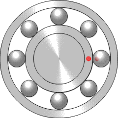
A ball bearing is a type of rolling-element bearing that uses balls to maintain the separation between the bearing races.

Fluid bearings are bearings in which the load is supported by a thin layer of rapidly moving pressurized liquid or gas between the bearing surfaces. Since there is no contact between the moving parts, there is no sliding friction, allowing fluid bearings to have lower friction, wear and vibration than many other types of bearings. Thus, it is possible for some fluid bearings to have near-zero wear if operated correctly.

<span class="mw-page-title-main">Bearing (mechanical)</span> Mechanism to constrain relative movement to the desired motion and reduce friction

A bearing is a machine element that constrains relative motion to only the desired motion and reduces friction between moving parts. The design of the bearing may, for example, provide for free linear movement of the moving part or for free rotation around a fixed axis; or, it may prevent a motion by controlling the vectors of normal forces that bear on the moving parts. Most bearings facilitate the desired motion by minimizing friction. Bearings are classified broadly according to the type of operation, the motions allowed, or the directions of the loads (forces) applied to the parts.

<span class="mw-page-title-main">Lubrication</span> The presence of a material to reduce friction between two surfaces.

Lubrication is the process or technique of using a lubricant to reduce friction and wear and tear in a contact between two surfaces. The study of lubrication is a discipline in the field of tribology.

<span class="mw-page-title-main">Plain bearing</span> Simplest type of bearing, with no rolling elements

A plain bearing, or more commonly sliding contact bearing and slide bearing, is the simplest type of bearing, comprising just a bearing surface and no rolling elements. Therefore, the part of the shaft in contact with the bearing slides over the bearing surface. The simplest example of a plain bearing is a shaft rotating in a hole. A simple linear bearing can be a pair of flat surfaces designed to allow motion; e.g., a drawer and the slides it rests on or the ways on the bed of a lathe.

<span class="mw-page-title-main">Rolling-element bearing</span> Bearing which carries a load with rolling elements placed between two grooved rings

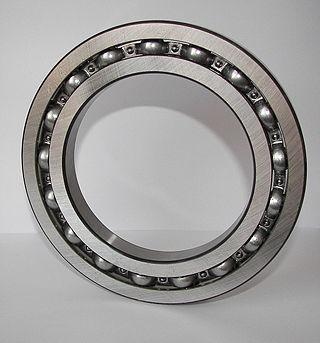
In mechanical engineering, a rolling-element bearing, also known as a rolling bearing, is a bearing which carries a load by placing rolling elements between two concentric, grooved rings called races. The relative motion of the races causes the rolling elements to roll with very little rolling resistance and with little sliding.

<span class="mw-page-title-main">Thrust bearing</span> Family of rotary bearings designed to support axial loads

A thrust bearing is a particular type of rotary bearing. Like other bearings they permanently rotate between parts, but they are designed to support a predominantly axial load.

<span class="mw-page-title-main">False brinelling</span>

False brinelling is a bearing damage caused by fretting, with or without corrosion, that causes imprints that look similar to brinelling, but are caused by a different mechanism. False brinelling may occur in bearings which act under small oscillations or vibrations.

<span class="mw-page-title-main">Yaw drive</span>

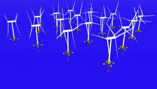
The yaw drive is an important component of the horizontal axis wind turbines' yaw system. To ensure the wind turbine is producing the maximal amount of electric energy at all times, the yaw drive is used to keep the rotor facing into the wind as the wind direction changes. This only applies for wind turbines with a horizontal axis rotor. The wind turbine is said to have a yaw error if the rotor is not aligned to the wind. A yaw error implies that a lower share of the energy in the wind will be running through the rotor area..

<span class="mw-page-title-main">Turbomachinery</span> Machine for exchanging energy with a fluid

Turbomachinery, in mechanical engineering, describes machines that transfer energy between a rotor and a fluid, including both turbines and compressors. While a turbine transfers energy from a fluid to a rotor, a compressor transfers energy from a rotor to a fluid. It is an important application of fluid mechanics.

Fretting refers to wear and sometimes corrosion damage of loaded surfaces in contact while they encounter small oscillatory movements tangential to the surface. Fretting is caused by adhesion of contact surface asperities, which are subsequently broken again by the small movement. This breaking causes wear debris to be formed.

<span class="mw-page-title-main">Tapered roller bearing</span> Type of roller bearing which can support axial loads

Tapered roller bearings are rolling element bearings that can support axial forces as well as radial forces.

<span class="mw-page-title-main">Unconventional wind turbines</span> Wind turbines of unconventional design

Unconventional wind turbines are those that differ significantly from the most common types in use.

A thrust block, also known as a thrust box, is a specialised form of thrust bearing used in ships, to resist the thrust of the propeller shaft and transmit it to the hull.

<span class="mw-page-title-main">Slewing bearing</span> Rotational support element for directional alignment

A slewing bearing or slew[ing] ring is a rotational rolling-element bearing that typically supports a heavy but slow-turning or slowly-oscillating loads in combination, often a horizontal platform such as a conventional crane, a swing yarder, or the wind-facing platform of a horizontal-axis (yaw) windmill. In other orientations they are used in materials handling grapples, forklift attachments, welding turnover jigs and so on.

A cam follower, also known as a track follower, is a specialized type of roller or needle bearing designed to follow cam lobe profiles. Cam followers come in a vast array of different configurations, however the most defining characteristic is how the cam follower mounts to its mating part; stud style cam followers use a stud while the yoke style has a hole through the middle.

<span class="mw-page-title-main">Yaw system</span>

The yaw system of wind turbines is the component responsible for the orientation of the wind turbine rotor towards the wind.

<span class="mw-page-title-main">Spherical roller bearing</span> Rolling-element bearing that tolerates angular misalignment

A spherical roller bearing is a rolling-element bearing that permits rotation with low friction, and permits angular misalignment. Typically these bearings support a rotating shaft in the bore of the inner ring that may be misaligned in respect to the outer ring. The misalignment is possible due to the spherical internal shape of the outer ring and spherical rollers. Despite what their name may imply, spherical roller bearings are not truly spherical in shape. The rolling elements of spherical roller bearings are mainly cylindrical in shape, but have a profile that makes them appear like cylinders that have been slightly over-inflated.

<span class="mw-page-title-main">Air bearing</span> Bearings with pressurized gas for low friction

Air bearings are bearings that use a thin film of pressurized gas to provide a low friction load-bearing interface between surfaces. The two surfaces do not touch, thus avoiding the traditional bearing-related problems of friction, wear, particulates, and lubricant handling, and offer distinct advantages in precision positioning, such as lacking backlash and static friction, as well as in high-speed applications. Space craft simulators now most often use air bearings and 3-D printers are now used to make air-bearing-based attitude simulators for CubeSat satellites.

Pitch bearing Component connecting a turbine blade to the hub allowing pitch variation

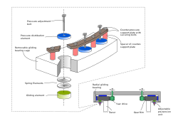
The pitch bearing, also named blade bearing, is a component of modern wind turbines which connect the rotor hub and the rotor blade. The bearing allows the required oscillation to control the loads and power of the wind turbine. The pitch system brings the blade to the desired position by adapting the aerodynamic angle of attack. The pitch system is also used for emergency breaks of the turbine system.

References

  1. 1 2 3 4 5 Molenbouw, A. Sipman, Zutphen, 2002, ISBN   90-5730-119-9

Further reading