Buffers and chain coupler

Last updated

Buffers and chain couplers (also known as "buffers and screw", "screw", "screwlink", and "English couplers") are the de facto International Union of Railways (UIC) standard railway coupling used in the EU and UK, and on some surviving former colonial railways, such as in South America and India, on older rolling stock. Buffers and chain couplers are an assembly of several devices: buffers, [1] hooks and links, or turnbuckle screws. [2]

Contents

On the modern version of the couplers, rail vehicles are mated by manually connecting the end link of one chain which incorporates a turnbuckle screw into the towing hook of the other wagon, drawing together and slightly compressing the buffer pairs, one left and one right on each headstock. That limits slack, and lessens shunting shocks in moving trains. By contrast, vehicles fitted with the semi-automatic Janney Type E coupler can experience significant jarring during mating and shunting. Very early rolling stock had "dummy buffers", which were simple rigid extensions of the frame, but they were improved with the use of enclosed mechanical, then hydraulic, springs to damp possible jarring. Each chain incorporates both a hook and a turnbuckle.

Characteristics

Screw-tensioned two-link coupling, shown attached but not yet tensioned. When tightened, the turnbuckle draws the buffers together, eliminating jarring and shocks when starting or slowing the train. The narrow buffers of the left-hand vehicle are sprung, the thicker buffers on the right contain a hydraulic damper. The sprung buffers allow for some train articulation even when the cars are drawn firmly together Carrage couplings on ABT Railway (3939380014).jpg
Screw-tensioned two-link coupling, shown attached but not yet tensioned. When tightened, the turnbuckle draws the buffers together, eliminating jarring and shocks when starting or slowing the train. The narrow buffers of the left-hand vehicle are sprung, the thicker buffers on the right contain a hydraulic damper. The sprung buffers allow for some train articulation even when the cars are drawn firmly together
Chain coupler detail (train in shunting mode) Chain coupler detail.jpg
Chain coupler detail (train in shunting mode)

The standard type of coupling on railways following the British tradition is the buffer and chain coupling used on the pioneering Planet class locomotive of the Liverpool and Manchester Railway of 1830. Those couplings followed earlier plateway or wagonway practice, but were made more regular.

The buffers and chain coupling is still the standard in European countries, except for the former Soviet Union, where the SA-3 automatic coupler is used. Coupling is done by a worker who must climb between the cars, who winds the turnbuckle to the loose position, and then hangs the chain on the hook. After that, the turnbuckle handle is stowed on the idle hook to prevent damage to itself, the vehicle, or the brake pipes. A dangling chain is only permitted during shunting. Disconnected brake pipes must be stowed on dummy connectors, to allow proper operation of the brakes. (The picture shows two coupled cars, with a single brake pipe.)

The hooks and chain hold the carriages together, while the buffers keep the carriages from banging into each other so that no damage is caused. The buffers can be "dumb" or spring-loaded. That means there are no run-in forces on the coupler. The other benefit compared with automatic couplers is that its lesser slack causes smaller forces on curves, so there is less probability of a broken coupler on a curve than with automatic couplers. The disadvantage is the smaller mass of the freight that can be hauled by hook and chain couplers, the maximum being 4,000 t (3,937 long tons; 4,409 short tons).

Early rolling stock was often fitted with a pair of auxiliary chains as a backup if the main coupling failed. That made sense before the fitting of continuous fail-safe braking systems.

On railways where rolling stock always pointed the same way, the chain might be mounted at one end only, as a small cost and weight saving measure.

On German and Scandinavian railways, the left buffer is flatter than the slightly more rounded right one, which provides better contact between the buffers than would be the case if both buffers were slightly rounded.

Variants

Three-link coupling on an antique tank wagon. There is no hook at the end of the chain, nor is there a turnbuckle. Consett-tankwagon41 - buffer beam.jpg
Three-link coupling on an antique tank wagon. There is no hook at the end of the chain, nor is there a turnbuckle.

A peculiarly British practice was the "loose-coupled" freight train, operated by the locomotive crew and a "guard" at the rear of the train, the successor to the brakesman of earlier times. That train type used three-link chain couplings for traction and side buffers to accept pushing forces but, since such trains were not fitted with an automatic through-train braking system, there were no pipes to connect between the vehicles. The last vehicle of the train was a heavily ballasted guard's van with its brakes controllable by a handwheel operated by the guard. The slack between vehicles was very convenient when starting heavy trains with a relatively low-powered locomotive on the level or on a rising gradient.

On the driver's command the guard would apply his brake as hard as possible. The driver would then gently reverse to close up the wagons onto their buffers. Then the locomotive was driven ahead, picking up the load wagon by wagon, thus giving an easy start up the gradient. Wagons of that era didn't have roller bearings and the grease-lubricated plain bearings exerted considerable resistance, especially on a cold day, so starting wagon-by-wagon greatly reduced the traction force required from the locomotive.

The disadvantage of that convenience was that the guard could get badly thrown about as the train changed speed due to the inter-wagon gaps opening or closing. In the worst case, the jerks could break a coupling or cause a derailment. A skilled guard would observe or listen to his train and apply or release his brake to keep the last few couplings reasonably taut, acting as a shock-absorber. The same effect occurred when the route changed gradient. When going over a hill the rear of the train would catch up with the wagons held back by the locomotive, but the guard could minimise that. That method of train working was why the guard, just like the driver, was required to prove his route knowledge before being given charge of a heavy train. Loose-coupled trains travelled at low speeds and were phased out in the 1970s. [3]

An improvement on the loose-coupled train is the "Instanter" coupling, in which the middle link of a three-link chain is specially triangular shaped, so that when lying "prone" it provides enough slack to make coupling possible, but when the middle link is rotated 90 degrees, the length of the chain is effectively shortened, reducing the amount of slack without the need to wind a screw. The closeness of the coupling allows the use of inter-vehicle pipes for train brakes. Three-link and Instanter couplings can be operated entirely from the side of the wagons, using a shunter's pole, which has a hook on the end, and is safer when shunting is being done. Similarly, the screw-adjustable coupler can be connected by a shunter's pole once it has been unscrewed. Ordinary three-link couplings have been superseded by instanter, screw or buck-eye couplers in UK freight trains today.

Center-buffer-and-chain(s)

Narrow gauge flat wagons, 750 mm (
.mw-parser-output .frac{white-space:nowrap}.mw-parser-output .frac .num,.mw-parser-output .frac .den{font-size:80%;line-height:0;vertical-align:super}.mw-parser-output .frac .den{vertical-align:sub}.mw-parser-output .sr-only{border:0;clip:rect(0,0,0,0);clip-path:polygon(0px 0px,0px 0px,0px 0px);height:1px;margin:-1px;overflow:hidden;padding:0;position:absolute;width:1px}
2 ft 5+1/2 in). Note the single buffer with a hook on the right side and a chain on the other Uzd7742.jpg
Narrow gauge flat wagons, 750 mm (2 ft 5+12 in). Note the single buffer with a hook on the right side and a chain on the other

On some narrow-gauge lines in Europe, and on the Paris Metro, a simplified version of the loose-coupler is used, consisting of a single central buffer with a chain underneath. Sometimes there are two chains, one on each side of the coupler. The chain usually contains a screw-adjustable link to allow close coupling. These variants are also used elsewhere. On sharp curves, a single centre buffer is less likely to be subject to buffer-locking. The Eritrean Railway also uses a centre buffer and chain coupler.

Buffer-and-chain on narrow gauge railways

Buffer-and-chain couplers are not suitable on lines with very sharp curves, because there is a buffer-locking problem if pushing the limit. Because of that, and because of Carl Pihl's successful promotion of the single-buffer Norwegian coupler that he designed to overcome the problem, conventional buffers-and-chain coupling is rarely employed on narrow-gauge systems, notable exceptions being the railway networks of Senegal/Mali, Tunisia and Côte d'Ivoire/Burkina Faso in Africa, and Queensland and Tasmania in Australia. Narrow gauge railways are often isolated from other railways, so standardization is not as important.

Problems with buffers and chain

Buffer-locking

Buffer-locking Ueberpufferung.png
Buffer-locking

On sharp reverse curves, the buffers can become locked by slipping over and onto the back of each other. Although careful track design makes this a rare occurrence, a series of derailments at Stuttgart Central Station in 2012 were caused by buffer-locked wagons. Buffer-lock could occur on very sharp switches on rolling stock with the older, rounded buffers. Newer buffers are rectangular and are wider than they are tall. Buffers and chain couplers allow curves to have around 150 m (492 ft) radius, but sharp S-curves are not allowed. If it weren't for the couplers, much sharper curves could be allowed, on the condition the train is not too long. [4]

Variation with gauge

The width between the buffers tends to increase as the track gauge increases and decrease as the track gauge decreases, which means that if wagons are changed from one gauge to another, the buffers might no longer match. That is because the buffers are originally extensions of the frames, which are spaced according to the gauge of the track. As well, the height of the buffers is usually lower on narrow gauge railways, corresponding to the generally lower height of the rolling stock. Therefore, narrow gauge railways often use centre couplers without buffers.

However, in the case of Iberian broad gauge railways, the height and spacing of the buffers are the same as for standard gauge railways in Europe including Great Britain, in order to allow through-running of rolling stock by the use of bogie exchange.

Dimensions

Buffers and chain couplers tend to have the two buffers spaced according to the gauge, but especially in Europe this is modified to the standard gauge value to allow interrunning by means of bogie exchange.

Dimensions showing variation of spacing by gauge:

NameGaugeHeightSeparationRegion
Standard gauge 1,435 mm (4 ft 8+12 in)1,054 mm (41.5 in)1,727 mm (68.0 in) [5] Great Britain, European mainland
Metre gauge 1,000 mm (3 ft 3+38 in)0,756 mm (29.8 in)1,248 mm (49.1 in) Senegal and Mali [6]
Burkina Faso and Ivory Coast.
Broad gauge 1,520 mm (4 ft 11+2732 in)1,063 mm (41.9 in)1,727 mm (68.0 in) Dual-gauge (Europe/Russia) sleeping car [7]
Broad gauge1,668 mm (5 ft 5+2132 in) Iberian gauge 1,050 mm (41.3 in)1,720 mm (67.7 in) Spain and Portugal
Broad gauge 1,676 mm (5 ft 6 in)1,067 mm (42.0 in)1,955 mm (77.0 in) India, Pakistan and Sri Lanka

See also

Related Research Articles

The Armagh rail disaster happened on 12 June 1889 near Armagh, County Armagh, in Ireland, when a crowded Sunday school excursion train had to negotiate a steep incline; the steam locomotive was unable to complete the climb and the train stalled. The train crew decided to divide the train and take forward the front portion, leaving the rear portion on the running line. The rear portion was inadequately braked and ran back down the gradient, colliding with a following train.

<span class="mw-page-title-main">Vacuum brake</span> Train braking system

The vacuum brake is a braking system employed on trains and introduced in the mid-1860s. A variant, the automatic vacuum brake system, became almost universal in British train equipment and in countries influenced by British practice. Vacuum brakes also enjoyed a brief period of adoption in the United States, primarily on narrow-gauge railroads. Their limitations caused them to be progressively superseded by compressed air systems starting in the United Kingdom from the 1970s onward. The vacuum brake system is now obsolete; it is not in large-scale usage anywhere in the world, other than in South Africa, largely supplanted by air brakes.

<span class="mw-page-title-main">Brake van</span> Car that had brakes used by Guards which is usually placed at the end of the Train

Brake van and guard's van are terms used mainly in the UK, Ireland, Australia and India for a railway vehicle equipped with a hand brake which can be applied by the guard. The equivalent North American term is caboose, but a British brake van and a caboose are very different in appearance, because the former usually has only four wheels, while the latter usually has bogies. German railways employed brakeman's cabins combined into other cars.

<span class="mw-page-title-main">British Rail Class 73</span> British bi-mode locomotive

The British Rail Class 73 is a British electro-diesel locomotive. The type is unusual in that it can operate from the Southern Region's 650/750 V DC third-rail or an on-board diesel engine to allow it to operate on non-electrified routes. This makes it very versatile, although the diesel engine produces less power than is available from the third-rail supply so the locomotives are rarely operated outside of the former Southern Region of British Rail. It is one of the first bi-mode locomotives ever built. Following the withdrawal and scrapping of the more powerful Class 74 bi-mode locomotives in 1977, the Class 73 was unique on the British railway network until the introduction of the Class 88 bi-mode locomotives in 2017. Ten locomotives have been scrapped.

<span class="mw-page-title-main">Railway coupling</span> Mechanism for connecting rolling stock in a train

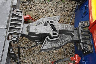
A coupling or coupler is a mechanism, typically located at each end of a rail vehicle, that connects them together to form a train. The equipment that connects the couplers to the vehicles is the draft gear or draw gear, which must absorb the stresses of the coupling and the acceleration of the train.

<span class="mw-page-title-main">Railway brake</span> Component of railway rolling stock

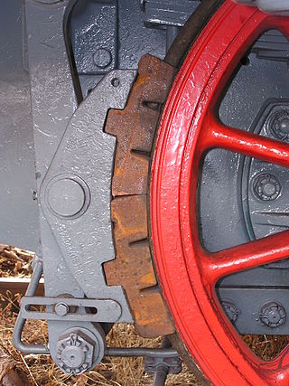
A railway brake is a type of brake used on the cars of railway trains to enable deceleration, control acceleration (downhill) or to keep them immobile when parked. While the basic principle is similar to that on road vehicle usage, operational features are more complex because of the need to control multiple linked carriages and to be effective on vehicles left without a prime mover. Clasp brakes are one type of brakes historically used on trains.

<span class="mw-page-title-main">Shunting (rail)</span> Process of sorting rolling stock into complete trains

Shunting, in railway operations, is the process of sorting items of rolling stock into complete trains, or the reverse. In the United States this activity is known as switching.

<span class="mw-page-title-main">Buffer (rail transport)</span>

A buffer is a part of the buffers-and-chain coupling system used on the railway systems of many countries, among them most of those in Europe, for attaching railway vehicles to one another.

This article contains a list of jargon used to varying degrees by railfans, trainspotters, and railway employees in the United Kingdom, including nicknames for various locomotives and multiple units. Although not exhaustive, many of the entries in this list appear from time to time in specialist, rail-related publications. There may be significant regional variation in usage.

Type H Tightlock couplers are a variety of Janney coupler, typically used on North American mainline passenger rail cars. They have mechanical features that reduce slack in normal operation and prevent telescoping in derailments, yet remain compatible with other Janney types used by North American freight railroads.

<span class="mw-page-title-main">SA3 coupler</span> Automatic coupler for railway use

SA3 couplers or Willison coupler and Russian coupler are railway couplings used primarily in Russia and states influenced by the former Soviet Union, such as Finland, Poland, and Mongolia.

In railroading, slack action is the amount of free movement of one car before it transmits its motion to an adjoining coupled car. This free movement results from the fact that in railroad practice cars are loosely coupled, and the coupling is often combined with a shock-absorbing device, a "draft gear", which, under stress, substantially increases the free movement as the train is started or stopped. Loose coupling is necessary to enable the train to bend around curves and is an aid in starting heavy trains, since the application of the locomotive power to the train operates on each car in the train successively, and the power is thus utilized to start only one car at a time.

The railcar couplers or couplings listed, described, and depicted below are used worldwide on legacy and modern railways. Compatible and similar designs are frequently referred to using widely differing make, brand, regional or nick names, which can make describing standard or typical designs confusing. Dimensions and ratings noted in these articles are usually of nominal or typical components and systems, though standards and practices also vary widely with railway, region, and era. Transition between incompatible coupler types may be accomplished using dual couplings, a coupling adapter or a barrier wagon.

<span class="mw-page-title-main">Barrier vehicle</span> Railway vehicle used to connect two others that have different types of coupling

A barrier vehicle (BV), barrier wagon, match wagon or translator coach is used to convert between non-matching railway coupler types. This allows locomotives to pull railway vehicles or parts of a train with a different type of coupler. A match wagon has an identical dual coupling at both ends.

Janney couplers are a semi-automatic form of railway coupling that allow rail cars and locomotives to be securely linked together without rail workers having to get between the vehicles. They are also known as American, AAR, APT, ARA, MCB, knuckle, Buckeye, tightlock, Henricot or Centre Buffer Couplers.

<span class="mw-page-title-main">Norwegian coupling</span>

A Norwegian coupling or coupler, is a manually operated coupling at each end of some narrow-gauge railway rolling stock. It consists of a central buffer incorporating a hook that drops into a slot in the opposing central buffer. The system is only found on narrow gauge railways with a gauge of 1067 mm or less on which low speeds and train loads allow a simpler system than, for example, knuckle couplers. Norwegian couplings are not particularly strong, and may be supplemented by auxiliary chains. Not all Norwegian couplings are compatible with one another since they vary in height and width. Some may permit a hook from both rail vehicles to be in place; others may be limited to one.

From time to time, a railway decides that it needs to upgrade its coupling system from one that is proving unsatisfactory, to another that meets future requirements. This can be done gradually, which can create many problems with transitional incompatibilities, or overnight, which requires much planning.

<span class="mw-page-title-main">Dual coupling</span>

Different types of railroad rolling stock have different couplers depending on the purpose and type of equipment being used and its intended destination. European rolling stock tend to use buffers and chain couplers while American rolling stock uses a Janney coupler or "knuckle coupler". These are incompatible with each other, but where some railroads have obtained older, less expensive used rolling stock from different countries or regions, instead of having to standardize on one form of coupler, it may be useful to be able to use either type of coupler on a piece of rolling stock without having to remove anything.

<span class="mw-page-title-main">British railway brake van</span>

British Railways inherited a variety of brake vans from each of the Big Four: GWR, LNER, Southern Railway and LMS due to the nationalisation of the railways in 1948.

<span class="mw-page-title-main">Balance lever coupling</span> Train buffer with couplings

The balance lever coupling, also known as rocking lever coupling or compensating coupling, is a type of central buffer coupling that has found widespread use, especially in narrow-gauge railways. In Switzerland this type of coupling is called a central buffer with two screw couplings, abbreviated to Zp2, or referred to as a central buffer coupling with coupling hooks on the side

References

  1. EN 15551:2009+A1:2010 Railway applications – Railway rolling stock – Buffers
  2. EN 15566-2009+A1:2010 Railway applications – Railway rolling stock – Draw gear and screw coupling
  3. "WSR :: West Somerset Railway :: Couplings". Archived from the original on 2006-09-26. Retrieved 2006-11-12.
  4. Green, J. I. T. (November 6, 1964). "Buffer Locking on Reverse Curves". Railway Gazette. 120 via trid.trb.org.
  5. Steam Spirit, Vol 1, p 129
  6. Jane's World Railways 1969-1970 edition
  7. Railway Gazette International Sept 2012, p 108